Laser based polymer welding in medical device manufacturing
The combination of pyrometer, galvo scanners, and diode laser systems optimizes welding results
By Jorg Neukum
Polymer welding in medical device manufacturing has special requirements as related to the colors of the materials, process control, and documentation of the process parameters. The usage of laser-based plastics joining brings in some aspects that make this joining method for particular applications advantageous compared to classical plastics joining methods like ultrasonic or heat-stamp. Some of the advantages of laser welding of polymers are:
- its excellent welding quality
- the protected welding zone (inside welding)
- the clean surfaces (no particles)
- the high optical quality of the seam
- the minimal thermal load to the workpiece
- easy designs (e.g., flat surfaces)
- the contact-free welding process (no deterioration of the welding quality)
- the online closed-loop process control and documentation
The online closed-loop process control and documentation of the parameters are possible by using high-power diode laser systems, which are available in the wavelength range between 640 nm up to 2 µm. The most prominent wavelengths for laser-based plastics welding processes are 810 nm, 940 nm, 980 nm, 1470 nm and 1940 nm. By the nature of the diode laser systems, direct modulation of the optical output power is possible via modulation of the electrical drive current and hence gives the fastest response.
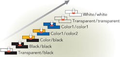
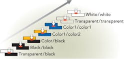
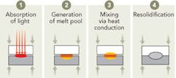
The colors of the materials involved determine the degree of complexity of the process itself. Except for the welding of two transparent materials, all other material combinations are joined using a sandwich of a “laser-transparent” part on top of a “laser absorbent” part (FIGURE 1). The laser is used to generate a melt pool in between the interfaces. Due to the absorption time and the generation of the melt pool, as well as for the wetting process of the melt pool onto the transparent plastic, such a process needs a certain time frame and cannot be done infinitely fast (FIGURE 2).
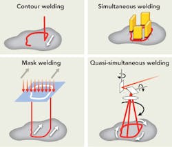
The various methods (FIGURE 3) used in laser-based plastics welding are:
- contour welding
- simultaneous welding
- mask welding
- quasi-simultaneous welding
The contour welding method is rather slow, but allows the controlled dosing of the applied heat to the work piece. The simultaneous welding method, however, is suited for fast and high-volume processes, but has the disadvantages of inflexibility and inhomogeneous heating along the contour. Mask welding is also inflexible since for each contour, a new mask is needed, and it consumes much more laser power than needed, making the process inefficient. The quasi-simultaneous welding method combines the contour welding with a fast galvo-scanning process. In combination with a pyrometer, the quasi-simultaneous method allows fast and precise welding with controlled heat and simultaneous storage of the relevant process data for quality control and traceability.
Process control
The closed-loop process control is based on pre-setting of welding temperatures, online measurement of the welding temperature, and online re-adjustment of the laser power if deviations occur between the set temperature and the measured temperature. In the comparison between the open-loop process and the closed-loop process, it can be seen that, in case of constant optical power, the temperature of the welding spot is rising all the time (FIGURE 4). If the process is not stopped, this will finally lead to the burning of the material. In the case of the closed-loop process, however, the power of the laser is always adjusted to keep the welding spot temperature close to the set temperature. If such a process continues, the laser power will drop to a level that is needed just to maintain the melt pool, yet overheating is prevented. This process can furthermore be performed with the optimum welding temperature.
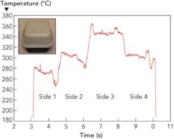
The example above can also be used to demonstrate further advantages of the closed-loop welding process. It was mentioned that the ripples of the signals are caused by the glass-reinforced PCB material used (FIGURE 5). A close look at the temperature profile at constant laser power for a single loop shows that – despite the fact that the welding seam has the shape of a symmetric square – the welding temperatures are different for the different sides of the square. A detailed examination has shown that this is caused by the orientation of the glass fibers inside the polymer matrix. Depending on the orientation of these, a part of the applied laser light is transported deeper into the matrix by the glass fibers. In such a case, the welding spot temperature will be lower than for those fibers that are oriented perpendicular to the light path.
It becomes obvious that such a material can only be welded with an optimized welding temperature when the laser power is online-adjusted; hence, the use of a diode laser system in combination with a pyrometer-galvoscanner option is absolutely necessary. A laser source at a fixed power level would never achieve a good welding result for materials with such an inhomogeneous surface absorption. Burst pressure tests have shown that a larger process window and higher burst pressures are achieved by using optimized welding temperatures.
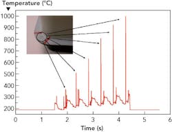
It is also apparent that the pyrometer signal cannot only be used for process optimization, but also for failure detection (FIGURE 6). In the example, a void in-between the two parts can be seen caused by a bubble during the molding process. This area of non-contact causes overheating, which, at the same time, can be detected as a spike in the temperature signal. Hence, such a part could be rejected or sent to the quality department for further examination.
Beam shaping
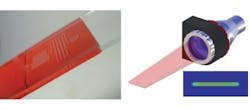
Beside applications with scanner and pyrometer, laser-based plastics welding can also take advantage of beam shaping of the laser beam. Examples can be homogenized beams with a line shape. In the device shown (FIGURE 7), a homogenized line source has been used to weld a microchannel structure used for lab-on-chip applications. Due to the fact that the beam is homogenized to a level of 95%, the welding is very homogeneous, even over a large area. Such homogenized line beams are available for fiber-coupled diode laser systems and can be customized to fit various geometries. For very large homogenized laser beams with a dimension of up to 600 mm, non-fiber-coupled, direct beam diode laser modules can be combined.
White and transparent materials
White polymers and transparent polymers are of high interest for applications in medical device manufacturing. These colors combined with the mentioned advantages of good seam quality and particle-free processes have a huge potential in medical device manufacturing. In this branch, the usage of special additives is not recommended because of the tedious approval procedures. Therefore, solutions are needed that definitively work without any additives, specifically those that will work with the material combinations that are already approved and used.
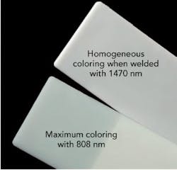
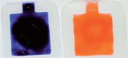
Fortunately for the welding of white polymers, the use of longer wavelengths, e.g., in the range of 1470 nm, allows a better usage of plastics with a better white color impression. In the example shown, a comparison is made between the achievable white color impression of two white polymers (FIGURE 8). One is welded with 808 nm, the other with 1470 nm. The welding at 1470 nm benefits from the fact that the approved substances used for the white color impression can be varied in concentration to allow “laser-transparent” and “laser-absorbing” properties at 1470 nm without influence on the white appearance in the visible.
For transparent plastics, the welding principle is completely different. Without additives such plastics normally do not absorb light from the visible range, even up to 1550 nm. That’s why we call them transparent. Yet, there is a chance to use the intrinsic absorption of polymers starting at a wavelength of approximately 1800 nm. The intrinsic absorption is caused by the vibrations of the polymer chains under the influence of the light >1800 nm. As the process happens in the bulk material and not at the surface, this is well-suited for foil welding or tube welding, resulting in a through-welding process (FIGURE 9). The foils are welded without pressure since the two foils have been in contact already due to electrostatics. After filling the bottle-shaped bag, the same laser at 1940 nm is used to hermetically seal the bag.
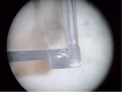
Another example of transparent welding (FIGURE 10) shows a microscopic view of a transparent Makrolon device. This cylindrical part has been welded on a rotary stage with 1940nm as well.
As mentioned, the absorption process in transparent polymers at wavelengths >1800nm is a volume effect. Hence, the inside welding of two transparent parts at their interface requires some thought. Yet, good results have been achieved using very large aperture optics with a short working distance. In such a set-up, the power is focused onto the interface, whereas, at the same time, the intensity and therefore the absorption in the volume of the material is much lower due to the lower power density outside of the focal spot.
Summary
Together with the already mentioned process advantages, diode laser systems with their properties of direct and fast modulation are the ideal laser source for plastics welding applications with seam widths in the mm-range, especially considering that there is a whole range of wavelengths for different applications available (640 nm up to 2000 nm). In combination with pyrometer and galvo scanners, diode laser systems can achieve optimized welding results with a high degree of quality control and process documentation, as required in medical device manufacturing.
It has been demonstrated that even materials with inhomogeneous surface absorption, such as glass-reinforced polymers, can be welded at optimized welding temperatures. Also, variations in surface absorption, e.g., by changing colors, can be compensated by using a pyrometer-galvo-scanner combination in conjunction with a diode laser system.
Diode laser systems also take advantage of the possibilities of beam shaping and homogenization, allowing an adaptation of the beam geometry to the application, such as large seam width or usage in mask welding methods.
White and transparent plastics are very important materials for medical device manufacturing. With the new wavelengths becoming available now, diode laser systems are used for those applications as well, allowing the end user to apply the benefits of laser-based plastics welding to white and transparent polymers.
Acknowledgments
The results described have been accomplished with contributions from Wolfgang Horn (Dilas Diodenlaser GmbH), Dr. Chul S. Lee (BASF Corporation), Rick Davis (Rofin-Sinar Inc.), and Dr. Alexander Savitski (Baxter Corporation).
Dr. Jorg Neukum is responsible for marketing and worldwide sales at Dilas Diodenlaser GmbH. He is also in charge of the business unit, Dilas Industrial Laser Systems.
