Laser metal forming with five axes simultaneously
Sulzer Innotec has been working with high-power lasers in material processing for more than 20 years. Laser metal forming, often also described as laser cladding, is successfully used for weld repairs, but is also being increasingly used in the production of new parts.
By Thomas Peters
In addition to lower distortion, the advantages of laser metal forming lie in the considerable improvement in the weldability of materials, even those that are difficult to weld, such as high-temperature nickel-base alloys and high-carbon steels. Well-known applications include repair welding on gas turbine blades or mold tools.
Principle of operation
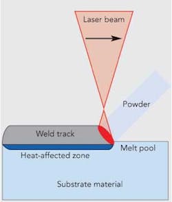
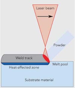
Laser metal forming is carried out using metal powder as filler material, which is fed to the melt pool created by the laser beam via a powder nozzle (FIGURE 1). Precise welding tracks can thereby be created using CNC control. The cladding of surfaces is possible just as well as buildup welding on webs and edges.
A powder feeder from Sulzer Metco is used to guarantee a constant and homogeneous flow of the metal powder. The powder is transported in adjustable quantity to the powder nozzle in a gas stream, whereby the inert carrier gas also serves as the shielding gas for the welding process.
Using a suitable powder nozzle, it is even possible to process titanium, which normally reacts very strongly to oxygen. In addition, as almost any material can be atomized, it is also possible to use the laser cladding technique with special materials that are not available as standard powders.
Considerations from the milling process
The production of impellers, whether in open design, with soldered or welded shroud, or integrally milled from a blank, is one of the core manufacturing competencies of Sulzer Innotec. This is accompanied by many years of experience in the programming of five-axis simultaneous milling processes, both with commercial CAM software and with in-house development.
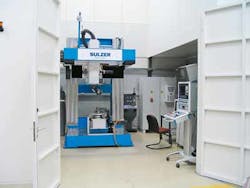
In laser welding technology, Sulzer Innotec operates a gantry robot with a 2.2 kW CO2 laser and a 1.5 kW fiber laser system (FIGURE 2), which both support the control of five-axis simultaneous machining. The idea of generating build-up welding tracks instead of milling tracks was thereby just as obvious as the first area of application — the restoration of the blade tips of exhaust gas turbochargers.
3D repair welding
In five-axis simultaneous machining, the tool, which would be the milling cutter in a milling machine or the laser beam and the powder nozzle in a laser welding system, can be continuously moved over the surface of the component on various programmed tracks at any angle of incidence. In the laser welding process, the laser beam is ideally mounted perpendicular to the workpiece.
In the exhaust gas turbocharger example, sufficient material is welded onto the curved surface of the turbine blade using the laser, and the original geometry is then restored by grinding or milling. The welding tracks are generated on the basis of the CAD model available in the CAD system.
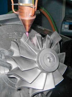
A robust welding strategy is just as important as robust welding parameters in order to compensate for the geometrical deviations of the cast wheel. In addition, a coaxial powder nozzle is used, with which a homogeneous weld buildup can be realized, regardless of the direction of the welding (FIGURE 3).
During the processing time on the fiber laser system, the processing head with the powder nozzle always points downwards, and thereby moves in three axes sideways and in height, while the component beneath it is simultaneously turned in two axes. Large workpieces that cannot be placed on the rotary-tilting table of the fiber laser system due to their weight will be machined in the gantry robot of the CO2 laser system. In this system, the two swiveling axes are located in the processing head, which can thereby be aligned to the fixed workpiece and be run at any desired angle of incidence.
Wear-protection coatings
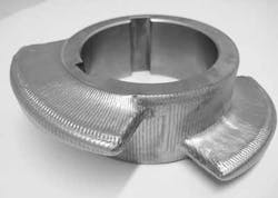
The application of wear-protection layers to any curved surfaces represents an interesting area of application for five-axis simultaneous machining. Stellites™ are hard alloys on the basis of cobalt and chromium, which, in addition to their great hardness, are also characterized by their high resistance to corrosion. When build-up welding a Stellite layer onto a feed screw (FIGURE 4), the complete coverage of the surface is therefore important. A careful selection of the welding process parameters will ensure a crack-free buildup.
Conventional build-up welding normally requires the preheating of the components and a subsequent heat treatment — process steps that can usually be omitted in laser metal forming. Due to the high level of dilution between the filler and the substrate material, several welding layers, or coating thicknesses of several millimeters, are also necessary in conventional welding in order to ensure the desired wear-protection characteristics of the functional surface. The low level of dilution during the laser cladding process, on the other hand, permits single-layer weld buildup, and thereby makes the coating of comparably thin-walled geometries possible in the first place.
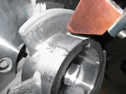
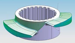
The accessibility of sharp edges, such as at the transition from the blade of the feed screw to the hub, thereby represents an additional challenge (FIGURE 5). In the picture, the powder nozzle is positioned exactly in the corner— just before the laser beam is switched on. The gas stream that transports the powder also ensures the cleaning of the melting area from previously deposited, excess powder remains. These are unavoidable, as the on-and-off switching of the powder flow will take considerably longer than the welding pauses, which only last a few seconds when the welding run is ended and the welding system is traveling to the start of the next welding track. These pauses can be optimized, however, by employing a well-designed welding strategy while programming the welding tracks in the CAD system (FIGURE 6).
Component armoring
In the case of extreme wear and impact loads, the build-up welding of layers with tungsten carbide in a cobalt or nickel matrix can be used, with which hardnesses of up to 1300 HV can be achieved. Here, too, the key to success lies in the comprehensive armoring of the surface of the component, especially in the corners and on the edges.
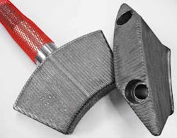
A crack-free weld result is not necessarily the most important factor. Instead, the correct selection of process parameters must ensure that the coating does not chip off following an impact. In the example given (FIGURE 7), teeth from a rock crusher are coated over the complete surface, as shown in the detailed photo (FIGURE 8).
The build-up welding once again takes place in a single layer on the welding tracks previously defined in the CAD system. In comparison with conventional build-up welding by hand, the process times are considerably lower, with an improvement in the layer quality at the same time. As a result of the even weld buildup close to the final shape, the reworking of the surface is considerably reduced or becomes completely unnecessary, which is a great advantage with such extremely hard materials.
Process qualification together with the customer
Process parameters for laser metal forming are not generally valid, but must be adapted to the material combination and the component geometry used in each case. Depending on the application, this can mean a process qualification in which samples are welded and metallographically investigated.
The long-term and well-documented experience in laser metal forming helps Sulzer Innotec to shorten the development process. The assessment of the welding result is carried out in accordance with the valid regulations in welding technology or according to the customer specification. The Welding Engineering department of Sulzer Innotec provides advice regarding material and process questions and, where necessary, can help the customer draw up an appropriate welding specification.
New possibilities
The use of laser metal forming is generally useful if competing processes, such as thermal spraying or conventional welding, prove to be technically unsuitable or if savings can be achieved in the pre- and postprocessing or in the design of the component. The 3D laser build-up welding with powder as filler material presented here makes it possible to process any component shape on the basis of a CAD model if the accessibility of the tool, in this case the laser beam and the powder stream, can be assured.
Welding in a single setup also significantly reduces the welding time, and thereby also the costs. The customers also benefit from the many years of industrial experience of Sulzer Innotec in laser metal forming with a wide range of materials and material combinations.
Thomas Peters is with Sulzer Markets and Technology AG, Sulzer Innotec, Sulzer-Allee 25, 8404 Winterthur, Switzerland; ph: +41 52 262 51 86; e-mail: [email protected]
**This article, which first appeared in the Sulzer Technical Review (3/2010), is reprinted with the permission of Sulzer AG, Winterthur, Switzerland.**
