Laser applications in nuclear decommissioning
The twin processes of concrete scabbling and tube cutting can be implemented for remote use in nuclear decommissioning environments
By P. A. Hilton and A. H. Kahn
This article and the accompanying video describe the results of a recently completed project to demonstrate the potential of high power lasers in aspects of nuclear decommissioning. In March 2009, the UK’s Nuclear Decommissioning Authority awarded TWI a contract to develop prototype equipment, in order to effectively demonstrate the twin processes of concrete scabbling and tube cutting and how these technologies might be implemented for remote use in nuclear decommissioning environments.
Contaminated concrete and pipework present major decommissioning challenges in terms of the total volumes of material to be treated, the radiation levels present, and the number of facilities affected. A number of concrete decontamination techniques have so far been evaluated and while water jetting or mechanical scabbling are favored options, each have drawbacks such as the generation of significant secondary wastes or the need for extensive control and deployment systems. Concrete decontamination by means of laser scabbling has the potential to avoid many of these drawbacks. As most of the contamination resides in a surface layer only a few mm thick, removing this means that the remaining concrete (often up to a meter thick) can be removed/demolished much more cheaply using conventional techniques.
However, while laser scabbling has already been demonstrated in the laboratory, see for example [1], to date, and no representative demonstration has been provided that would give industry confidence in using the technique. Although cutting of pipes has been performed on numerous occasions, most of the techniques employed are slow to operate or are not suitable for remote deployment in highly active cells. Laser cutting is well suited to remote deployment, due to the availability of light and compact process heads, the lack of reaction force between such heads and the tube, and limited fume generation. [2]. However, as with laser scabbling, the process needs to be adequately demonstrated before active deployment will be seriously considered.
Chosen laser source
A key parameter in most laser processes is, of course, the power density in the beam applied to the surface of the material in question. The two processes of concern in this project were unusual in that laser cutting requires a very high power density in the beam, whereas laser scabbling requires a relatively modest power density. For this work, because of the former requirement, the need for an efficient, robust, and compact laser source and the need, in remote applications, for optical fiber delivery of the laser beam power, a 5kW multimode industrial fiber laser was chosen.
The performance of the laser was monitored using a laptop computer, which also provided detailed information about the operating status of the laser. Control of the laser was routed to the controller of the deployment system in use, in this case an articulated arm robot. A beam switch unit directed the laser power to either the scabbling system or the cutting system as required, using fibers of 0.6 mm and 0.15 mm in diameter, respectively.
Single-sided laser cutting
Laser cutting of flat plate and tube are very well established manufacturing processes and account for the largest use of high power lasers. The majority of work performed is the cutting of material up to about 20 mm thick, with exceptional quality of the resulting edge. In conventional tube cutting, the tube rotates under the laser beam. For single-sided tube cutting, where the tube is fixed in space, alternative approaches are required.
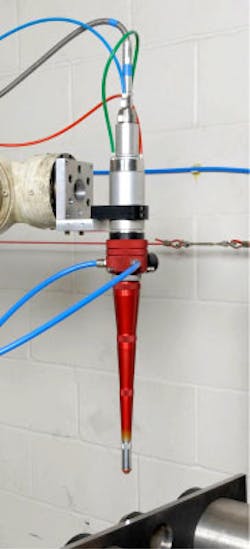
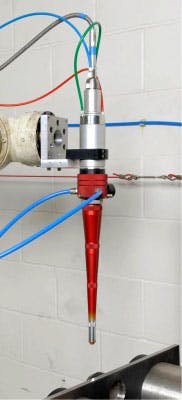
The system used in this work is unusual in that its focusing lens had a long focal length of 500 mm. The effect of this was to produce a very narrow beam with a large depth of focus. This large depth of focus is a major contribution to the process of single-sided tube cutting. The laser beam was enclosed by a cutting nozzle and a nozzle tip with an exit diameter of about 5 mm. In contrast to conventional laser cutting, for tube cutting, the laser beam focus was positioned about 90 mm below the tip of the nozzle, allowing tubes up to 170 mm in diameter to be cut from one side. The cutting process was also assisted by a jet of air at high pressure, which exited the nozzle concentric with the laser beam. This compressed air was necessary to blow away material in the kerf of the cut, melted by the laser beam and is also particularly important for single-sided cutting in order to achieve separation of the tube. The cutting head can be seen in FIGURE 1. This cutting system could also be equipped with a camera, which looks directly through the cutting nozzle, focusing at approximately the same point as the laser beam. This is useful in remotely positioning the cutting head above the tube to be cut. For the work described here, the cutting head was manipulated by an articulated arm robot. All movement of the process head and hence the laser beam, switching of the compressed air, and control of the laser was achieved through the robot controller.
Using this equipment, various options for single-sided tube cutting were possible. Stainless steel tubes from 25 to 170 mm in diameter, with a range of wall thicknesses from 1.5 to 11 mm, were cut using single pass, two pass and multiple pass techniques. Generally speaking, a two pass technique proved the most efficient for all but the smallest diameter tubes. If the cut edge of a tube is examined, it is clear that the quality of the cut at the side closest to the cutting head is much cleaner than at the opposite side. This is because, on the first pass, most of the energy in the laser beam and the assist gas are used to cut material originally contacted by the beam. Only laser energy and gas that have passed through the upper section of the cut are available to address the lower section and this is cut less effectively. For the second pass, a kerf has been previously opened in the top section and now the majority of the laser energy passes through this and acts more effectively on the lower section of the tube. As an example of performance, FIGURE 2 shows the dependence of the maximum cutting speed at which the tube is severed as a function of laser power.
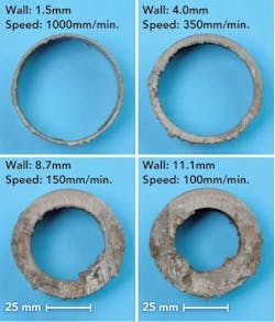
The results shown are for a tube of 155 mm diameter and 1.5 mm wall thickness, for two pass cutting, but similar trends were observed for other diameters and walls. Note that the cutting speed is fairly linear with applied power, at least up to 5 kW. The optimum assist gas pressure appeared to be about 8 bar. FIGURE 3 shows cut sections from 60 mm diameter tubes, with wall thicknesses from 1.5 to 11 mm, again for two pass cutting. Process parameters can be found in the figure. In this series of cuts, the only parameter to be varied was the process speed, which was 10 times faster on the 1.5 mm wall, compared to the 11 mm wall.
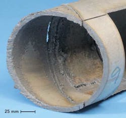
However, it should be noted that all the different wall thicknesses could also be cut at a speed of 100 mm/min, thereby allowing cutting of all these tubes without any change at all in the process parameters. The largest tube to be cut in this work had a diameter of 170 mm, with a 7 mm wall thickness and is shown in FIGURE 4.
This is not believed to be the limit for the laser in use. To go above this diameter, a shorter nozzle assembly would be needed. Using a three pass technique, the tube was severed in a time of 7 min using 4.8 kW of laser power. Another possibility demonstrated was the cutting of concentric tubes. For example, a 25 mm diameter tube located inside a 60 mm diameter tube. In this case a two pass technique was effective in severing both tubes at once.
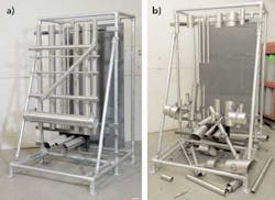
In order to simulate a possible arrangement of different diameter tubes in different locations and with different packing density, the assembly of tubes shown in FIGURE 5a was constructed. Over 50 cuts were employed to demolish this assembly of tubes ranging from 25 to 155 mm in diameter, including tube severance, fixture severance, and hole cutting (in the larger diameter tubes). The assembly was reduced to the state shown in FIGURE 5b in one continuous cutting sequence lasting just over 15 minutes.
Concrete scabbling
In the laser scabbling process, the laser beam is applied to the surface of the concrete and its energy is absorbed, heating the concrete matrix and the concrete aggregate. Expansion of residual water vapor, probably in both the matrix and aggregate and differential expansion between aggregate and matrix causes the concrete to break up in a highly energetic fashion, leaving a rough scabbled surface, consisting of matrix and aggregate.
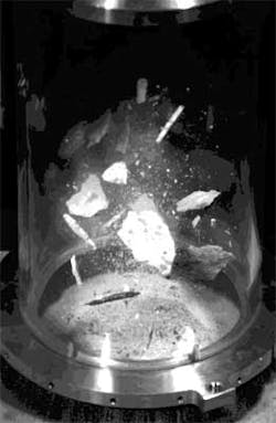
FIGURE 6 shows a still image taken from a high speed video of the process, showing the energetic nature of the scabbling, in this case, the concrete contained limestone aggregate. In the video image, taken through a polycarbonate tube, the laser beam is incident downwards and has a diameter of about 60 mm when its hits the concrete surface. From successive images, it was possible to calculate the speed of the concrete particles leaving the surface to be about 18m/sec.
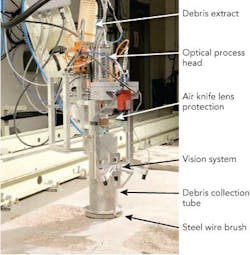
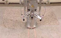
In any effective use of this process for decontamination, clearly the laser beam must move with respect to the concrete surface and the ejected debris must be contained. In this work, the former was achieved by the use of an articulated arm robot and the latter by enclosing the process and using a large pump and filtration system to recover the debris. The scabbling head's major components can be seen in FIGURE 7.
In the scabbling system, the laser light was fed, via an optical fiber, to a set of optics similar to those used for laser cutting, although in this case the focal length of the lens used was much shorter. The laser light was brought to a focus at a small diameter aperture and then allowed to expand to a diameter of about 60 mm at the base of a debris recovery tube. This tube, about 150 mm in diameter, was terminated round its circumference by a steel wire brush, in contact with the concrete surface. The aperture and the region through which the beam passed below the focusing lens were both protected by jets of compressed air. On this system, the air pressure and any possible contamination of the optical elements were continuously monitored. If contamination occurred, a warning signal was automatically generated. If the compressed air failed, the laser beam could not be released.
The top of the aluminium tube was connected to a long flexible hose and hence to a pumping system, which removed the concrete debris as it left the surface of the material. The complete scabbling head was mounted on the arm of an articulated robot, which was itself mounted on a linear gantry some 6 m in length. The scabbling process and effective debris removal requires the process head to be at all times roughly perpendicular to and at a constant distance from the concrete surface. The 6 axes of motion offered by the robot allow this to be achieved. However, the scabbling head was also equipped with its own vision system. A combination of low power lasers and a camera were mounted on the side of the scabbling head. The information recorded by the camera is interpreted by software and the results fed back automatically to the robot controller.
In this way, once a scabbling area has been set and the head driven to its approximate start position, the vision system and its feedback to the motion controller of the robot will automatically maintain both the attitude of the head perpendicular to the concrete surface and a constant stand-off distance, as the scabbling process proceeds. A large 16kW motor powered the vacuum system that removed the concrete debris. Air was sucked in at the base of the scabbling head, through the wire brushes. This air draws the concrete debris into the flexible tube and down to the first stage of an enclosed separation process. Concrete particulate matter was deposited in a first container and concrete dust was collected via a filter in a second container. The body of the pumping unit also contained two additional housings capable of containing HEPA filters. The efficacy of the debris removal system was high, with hardly any scabbled material remaining on the concrete regardless of its orientation. FIGURE 8 shows the typical debris collected in the container. Some of the debris leaving the concrete surface was up to 20 mm in size. However, motion through the system reduced the size of the particles and the resulting debris had a high packing density.
For a given laser spot size on the concrete, the main process parameters are the laser power and the travel speed. Work performed has indicated that removal rate is proportional to laser power, at least up to the 5 kW of power available with the laser being used. At 5 kW power, this system has removed 1 m2 of material, to a depth greater than 10 mm, in a time of 110 min. A single pass of the process results in a scabbled ‘trough’, lenticular in section. This shape is related to the energy distribution in the incident laser beam, which at the concrete surface is Gaussian in form regardless of the fiber delivery. A slower process speed will generally result in a deeper scabbled section. For concrete containing limestone aggregate, the deepest section has been measured at 22 mm, using a laser power of 5kW and a travel speed of 100 mm/minute. For removal of large surface areas, a track overlap of 50% proved to be the most effective for producing a uniform depth in the scabbled profile. The process appeared independent of the attitude of the concrete. FIGURE 9 is a still image taken from a video sequence showing the system operational in the removal of a 1 m x 1 m square section of concrete to a minimum depth of 10 mm, using a single pass. Note the effectiveness of the debris removal system.
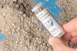
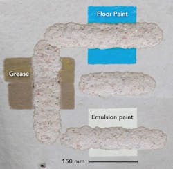
Re-scabbling over an existing track is possible and does result in an increased removal rate. However, in multi-pass processing of the same track, the amount of concrete removed was seen to drop at each successive pass. For example, at 5kW laser power and 300 mm/minute travel speed, the maximum depth of scabbling recorded for three successive passes of the beam was 10 mm, 18 mm, and 22 mm, respectively. Surface contaminants such as grease and paint (FIGURE 10) had no effect on the scabbling process.
Conclusions
For concrete with a limestone aggregate, a 5 kW laser will remove 1 m2 of surface to a minimum depth of 10 mm in under two hours. Coverage can be increased by either reducing the depth of removal or by increasing the laser power. For other types of aggregate, which show less reaction to the laser than limestone, scabbling is not as effective and further work is required to optimize performance.
A very effective and efficient system for cutting of stainless steel pipes and other fixtures/fittings has been developed. The cutting head is both lightweight and has a significant stand-off tolerance, so is relatively simple to remotely deploy and operate.
Acknowledgments
The authors are grateful to the Nuclear Decommissioning Authority for funding the work reported in this article and for giving permission for its publication.
References
1. E. P. Johnston, G. J. Shannon, W. M. Steen, and J. T. Spencer, "Surface treatment of concrete (scabbling) using high power CO2 and Nd-YAG lasers," ICALEO, San Diego 17-21 Nov. 1997.
2. C. Chagnot, G. de Dinechin, G. Canneau, and J-M. Idasiak, "Dismantling nuclear power plant with new industrial cw Nd:YAG high power lasers," Proceedings of Global, Paris, France, Sept 2009, Paper 9539.
P.A. Hilton and A. Kahn are with BWI, Granta Park, Great Abington, Cambridge, CB21 6AL UK. For further information, please contact Hilton at TWI at [email protected] or Khan at [email protected].
