High quality ablation using a single mode fiber laser
A modulated regime can improve the material removal rate in stainless steel
By Mohammed Naeem and Stephen Keen
Abstract
Low power (up to 500 W) single mode Ytterbium fiber lasers operating at 1080 nm with a very good beam quality (M2 ~ 1.10) are routinely being used for a range of micromachining applications.
The high brightness of the fiber laser enables high power densities even at modest power levels, which is sufficient for cutting a range of thin metals, capable of welding of various materials, including high reflective material, and also drilling small holes in metals, including aerospace alloys.
To date, very little work has been carried out with these lasers for ablation applications. The laser ablation of metals is normally carried out with Q-switched pulsed lasers ranging from microsecond to femtosecond pulse durations, pulse frequencies up to 50 kHz, and extremely high peak powers (MW).
In this work, laser ablation of a variety of materials including TBC super alloys used for aerospace has been demonstrated with a single mode fiber laser up to 400 W. The paper will investigate the material removal rates and ablation quality.
Introduction
The low power fiber lasers are very compact, robust, and have an edge over lamp-pumped Nd:YAG lasers in terms of beam quality and wall plug efficiency (approx 20%).
Current investigations [1–3] show that the single-mode fiber laser is an efficient, reliable, and compact solution for micro-cutting and micro-joining. The diode-pumped technology offers low maintenance cycles and high conversion efficiency. Theoretical pump-light conversions of more than 80% are possible [4], but typical optical conversion efficiencies for Ytterbium double-clad fiber lasers are 60–70% [5].
An area where there is a significant difference between lamp-pumped YAG and fiber laser performance is pulsed operation. Lamp-pumped lasers are capable of producing long, multi-ms pulses with peak powers many times the rated average power of the laser, provided that the duty cycle is sufficiently low. This ability stems from the flash-lamp itself, which is often more constrained by the maximum average thermal load than the peak power output.
By contrast, while the semiconductor laser diodes used to pump a fiber laser can be on-off modulated over a wide frequency range as shown in FIGURE 1 (from DC to tens of kHz in most industrial applications), they cannot typically be over-driven for long periods (multi-ms) in the same way as a flash-lamp without reducing the lifetime of the device to an un-acceptable level.

From an applications perspective, this regime can enhance laser material processing in terms of processing speed, weld penetration, and cut quality [6]. This paper describes the use of different modulation regimes with the JKFL200 to achieve high material removal rates. The modulation regime can improve the removal rate by 8x compared to running the laser in a purely continuous mode (CW).
Experimental work
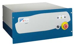
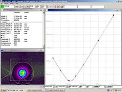
The ablation tests were carried out with a 400 W single mode Ytterbium fiber laser (FIGURE 2) operating at 1080nm wavelength that emits a Gaussian beam with a M2 < 1.10 (FIGURE 3). The laser was fitted with a JK Lasers scanning head, and the results reported are at an average power of 200 W.
The laser was operated CW and modulated with a 20–35 µsec off time at a frequency of 5+ kHz. Typical drive waveform is highlighted in FIGURE 4, and pulse is shown in FIGURE 5.


FIGURE 6 shows energy calculations in the pulse waveform. Energy in relax pulse = peak power x duration = 600 nsec x 800 W = .48mJ. Energy in rest of the pulse = ton x average power = ton x 200.

FIGURE 7 shows the estimated percentage of the entire waveform that is made of the relaxation pulse and the average power variation with frequency for a 20 µsec pulse. The graph shows that for frequency of 5 kHz, the relaxation pulses only make up 1.3% of the total energy, whereas for the 35 kHz frequency, it is 28%.

FIGURE 8a shows the optical set-up for the ablation experiment. A 4 mm square was repetitively scanned with the pattern shown in FIGURE 8b. Speed = 1250 mm/sec, Step 0.24.

The spot sizes used during these tests are highlighted in the TABLE.
| Output | 30 μm spot | 50 μm spot |
| 200 W CW | 28 MW/cm2 | 10 MW/cm2 |
| Modulated | 112 MW/cm2 | 40 MW/cm2 |
Results and discussion
Stainless steel
The metal was exposed for 26 sec and weighed before and after to quantify the amount of material removal. FIGURES 9a and b show mass removed as a function of average power and modulation frequency, respectively.

Results show that a mass of 80 mg in 26 sec, which corresponds to 184 mg/min or, given the density of stainless steel, 8030 kg/m3, 8.03 mg/mm3. This gives a material removal rate of 23 mm3/min.
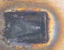
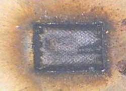
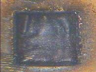
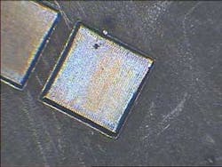
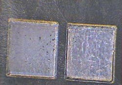
The results also show that in the modulated regime, the mass removed is 8x greater than that achieved with a pure CW output. The average power is decreasing due to altering the frequency of the off time of the laser. The increased material removal rate is due to the high peak power in the relaxation pulse. FIGURE 10 shows the ablated surfaces of 304SS at different laser parameters:
TBC coated materials
Thermal barrier coatings are being widely applied in many types of engines and in aircraft's gas turbines. To increase temperature capability of the engine blades and vanes, a thin coat of a heat-insulating zirconia ceramic is applied on the surface of the blades as a thermal barrier coating.
The cooling of the components causes a pronounced reduction of the metal temperature, which leads to a prolongation of the mechanical component's lifetime. Alternatively, the use of thermal barrier coatings allows raising the process temperature, obtaining thus an increased efficiency.
Thermal barrier coatings usually consist of two layers (duplex structure). The first layer, a metallic one, is the so-called bond coat, whose function is, on the one side, to protect the basic material against oxidation and corrosion and, on the other side, to provide with a good adhesion to the thermal insulating ceramic layer. Such a ceramic coating is mostly made of yttria partially stabilized zirconia (YSZ) since this material has turned out particularly suitable during the last decades.
At present, there are two principle methods of applying thermal barrier coatings: plasma spraying and electron beam physical vapor deposition (EBPVD). These methods have been studied excessively to avoid mechanical and adherence problems between coatings and substrate.
Current practice in drilling TBC materials is to remove the coating with either a Q-switched pulsed Nd:YAG laser (short pulse width and high peak power) or use a pulsed fiber laser.
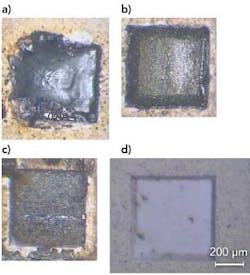
In this work, a CW fiber laser was used to remove the TBC coating on aerospace alloys. FIGURE 11 highlights the results on the coated aerospace materials, while FIGURE 12 shows the results on uncoated aerospace materials.
Summary
The ablation work with a 200 W CW fiber laser has shown:
- a modulated regime can improve the material removal rate in stainless steel by 8x
- a removal rate of 184 mg/min equivalent to 23 mm3/min cf Powerlase paper, which quotes 10 mm3/min for a Q-switched laser
- better finish in the modulated regime, and
- TBC coating cleanly removed.
References
1. Naeem, M, "Micromachining with a single mode 100 W fiber laser," Conference Proceeding LAMP 2006, Kyoto Research Park, Kyoto, Japan, May 16-19, 2006.
2. Naeem M, Lewis S, "Pulsed Nd: YAG laser or continuous wave fiber laser for micromachining?" Proceedings of the Fourth International WLT-Conference on Lasers in Manufacturing 2007, Munich, June 2007.
3. Naeem, M, "Microwelding performance comparison between a low power (125 W) pulsed Nd:YAG laser and a low power (100-200 W) single mode fiber laser," Conference Proceeding PICALEO 2008, Beijing, China, April 2008.
4. Reichel, V, Unger, S, Hagemann, H, Auerbach, M, "8 W highly efficient Yb-doped fiber laser," Proceeding of SPIE, Volume 3889, 2000.
5. Nilsson, J, Grudinin, A.B, Turner, P.W, “Advanced pulsed and CW high-power fiber laser,” CLEO Proceedings, 2000.
6. Naeem, M, "Modulation techniques for enhanced material processing using a single mode fiber laser," Conference Proceeding ICALEO 2008, Temecula, CA, USA, October 20-23 2008.
Dr. Mohammed Naeem ([email protected]) and Stephen Keen are with JK Lasers, Rugby, UK.