Quality inspection for remote laser applications
By Thomas Grünberger and Daniel Nufer
Industrial production processes need quality inspection systems corresponding to national, international, and company standards. This also holds for innovative laser material processing such as remote laser welding applications. In addition to concepts like performing a sample check using visual or destructive testing techniques, there exist several possibilities to do a 100% check of all welding procedures. This leads to more reliable and safer production with the benefit of less cost at the same time. This article presents two concepts of non-destructive testing techniques that perform a 100% quality inspection of remote welded seams.
Remote welding
Remote laser welding systems consists of a laser with high beam quality and a scanning welding head that performs local deflection of the laser beam in the given work space of the scanner at high focal length. For global positioning of the welding head, this concept can be implemented using robots or, for example, linear axle systems, enabling the user to perform laser material processing in 2D, 2½D, or 3D.
This remote laser welding process has numerous advantages: less time between seams, high laser on-time, high geometric flexibility. and precise positioning.
Different systems are available in the market using different laser sources (CO2 laser, fiber laser, or disc laser) and welding concepts like robot guided scanners and welding on-the-fly.
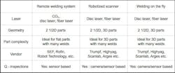
Table 1 shows typical remote welding systems and available quality inspection techniques (sensor or camera based).
Table 1. Excerpt of available remote welding concepts
Quality inspection of welding seams
Beside concepts like performing a sample check, there exist several possibilities to do a quality inspection of welded seams. There are well known non-destructive testing (NDT) methods based on standards such as ISO9712, like eddy current, ultrasonic, visual, or radiographic testing methods.
The effort for automated test procedures is very high, and an online solution is not possible to implement, so the quality feedback loop is longer compared to online solutions. The great benefit of using such systems properly is to produce higher quality at less production costs.
30 percent cost savings. Sensor- and camera-based process monitoring systems recognize production failures in real-time. Therefore, the manufacturing costs in many cases are reduced by up to 30 percent through elimination or reduction of: follow-up costs that originate through finishing, call-backs and delivery of faulty prefabricated parts. This is achieved through fully automated quality inspection and the possibility to optimize the production process.
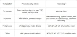
Test positions for quality inspection of welding seams. Three test positions are possible, according to requests, in order to guarantee the quality of welding seams in the plant: pre-process, in-process, and post-process. Additionally, there is the option to do an offline test in a dedicated inspection station later on (see Fig. 1).
Figure 1. Test position: pre-process, in-process, and post-process.
In the pre- and post-process sector, camera-based solutions are dominant. Sensor based solutions have become generally accepted for inline-testing (in-process). The primary advantage of a sensor-based solution is its robustness and fast processing speed yielding, in real time, calculations of the OK/NOK results. The integration costs for offline testing are high compared to the inline variants as integration of an additional workstation is not required; also, the needed space for installation of offline systems is much higher. Table 2 gives an overview of the principal quality criteria and technologies depending on the test position.
Table 2. Quality criteria and possible technologies test positionVisualization, detection of defects, traceability. Due to the demand for high-quality product in large volume, fully automatic solutions in the area of process control and quality assurance are required. The visual inspections of the welding seams are cost-intensive and, measured at current quality standards, are not sufficiently reliable. Sensor- and camera-based test methods offer solutions for most technical challenges. An overview:
1. Visualization of the processes
* Statistical analysis of the processes
* Identification of trends to avoid defects
* Improvement in the process comprehension of operators
* Recognition of systematic faults
* Recognition of potential for improving production
* Reduction of maintenance time
2. Defect detection through OK/NOK decisions
* Definition of defects
* Discharge of defective components directly during or after the process
* 100% inspection of all seams
* Fatigue-proof and objective
* Setup of a rework procedure
3. Traceability of components and production steps
* 100% documentation of the quality of seams, full traceability possible
* Current control of the contexts of several production steps
* Additional analysis and definition of critical components
A typical definition of process risks is shown in Figure 2.
Figure 2. Definition of different risk levels.
Contactless real time in-process monitoring systems
The quality of the laser welds for remote welding is monitored in-process, in real time using either a camera based or a sensor-based solution. This approach is contactless and non-destructive and provides 100% documentation of the inspected welds. The systems can be easily integrated into a remote laser head. The parts need a different test procedure as the welding defect definition and traceability can be widely different for different applications. In the project, an impact analyses and a risk assessment should be done according to the requirements. It is obvious from Table 2 that the selection of the test equipment should be done on the basis of a welding defect catalog.
Figure 3. Sensor-based and camera based solutions.
Camera based solution: plasmo® high dynamic observer. Classic NDT test method infrared testing (IT) is well known where energy is directed into a test probe and the temporal, spatial, and temperature distribution of the probe is measured. In case of laser processing, this energy is already put in the material during the welding process.
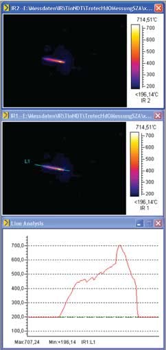
The temperature distribution of a typical welding process is shown in Fig. 4. The measurement was done with a standard infrared camera responsible in the wavelength region from 8 to 14 µm.
Figure 4. Temperature distribution of a typical laser welding measured 100 ms after the welding.
Such infrared cameras are expensive and can’t be used at the camera adapter of a remote welding head due to the transmission properties of the optical path.
Looking at the temperature values in Fig. 4, it can be seen that there are temperatures above 400°C/752°F. These temperatures can be visualized using a CMOS camera responsible in the near infrared range (NIR) from 700 to 900 nm (refer to Planck’s law), where typical remote welding heads are transmissive. In the case of the plasmo high dynamic observer, a special CMOS camera is used that is very sensitive in NIR, offering a high dynamic range of 170 dB in rolling shutter mode.
The camera is positioned on the side to the laser beam and mounted to the camera adapter of a remote welding head. Measured in this application is 20 mm long C shaped welding on zinc coated steel (thickness of 1 -3 mm, laser power nominal 2kW nominal welding speed 2 m / min). Directly after the welding the remote scanner moves back in the center of the welded figure and a trigger pulse is sent to the camera to take an image (this can be done by monitoring a CAN bus protocol (as shown in Fig. 5) if available in the scanning head or done by the scanner PLC directly.
A typical system layout is shown in Fig. 5. The next section presents typical detectable defects.
Figure 5. System layout plasmo high dynamic observer.
Welding defects, such as disjoints in positioning and partial weld-throughs, are identified with the high dynamics camera, which identifies changes in the heat distribution at the workpiece. The patterns indicating defects are clearly readable - welded yes or no, weld length, cut upper sheet, and even false friends as shown in Table 3. The characteristic of the cool down phase of a weld can be shown shortly after the welding process. The brightness corresponds with the heat in welding seam. The temperature difference from the start of the seam to the end the seam can be clearly proven.
Table 3. plasmo® high dynamic observer: Example images of welding defectsSensor-based solution: plasmo® process observer advanced. During the welding process, different process emissions will appear in different wavelength regions. These emissions are in the infrared, visible, and ultraviolet wavelength ranges.
Figure 6. System layout plasmo process observer advanced.
Welding defects are expressed through changes in process emissions. The emitted process light is captured by an optical fiber and is transferred to the evaluation hardware. This sensor detects the radiant power in two different wavelength ranges: visible and near infrared. This signal is analyzed by five different algorithms:
* Threshold: laser power on workpiece
* Duration: max. and min. welding length
* Absolute limits: geometric defects
* Adaptive limits: short-term fluctuations
* Signal dynamics: lack of fusion, “false friends”
Recognizable effects are:
* Pores
* Seam narrowing
* Ejections
* Changes in welding depth
* Lack of fusion
* Impurities
* Changes in laser power
* Changes in welding speed
* Incorrect gap
Table 4: plasmo® process observer: Cross-section and corresponding signal data
Summary
Today the quality inspection of laser welds is being monitored on-line, in real time, using diode based solutions or special CMOS cameras that are very sensitive in NIR. The approach is contactless and non-destructive for both solutions and provides a 100% documentation of the monitored weld seams for remote welding tasks. Both solutions can be easily integrated into standard remote laser heads and adapted to a company's weld quality assurance program. The solutions have demonstrated how to use the technology in 24/7 operations in the automotive and sub-supplier industry. The plasmo® high dynamic observer and also the plasmo® process observer are capable of accepting or rejecting weld seams during the production cycle in real time. The great benefit of using such systems properly is not to produce higher quality; more essentially, it permits understanding of the relationships of the manufacturing parameters and their measurable quality.
plasmo Industrietechnik GmbH is a global high-tech provider of automated quality assurance systems for the manufacturing industry. Founded in 2003, it is based in Vienna and has a network of international distribution partners. The company’s expertise ranges from laser power measurement, welding process control, monitoring of weld seams, geometric forms and surfaces, and tailor-made industrial imaging solutions to analysis software. It is a market leader in the real-time quality inspection of joining processes. Its large international customer base includes: steel companies, such as Thyssen, Salzgitter, Tokyu Steel and Posco, and motor vehicle manufacturers, such as Audi, BMW, Daimler, PSA, Suzuki, and Volvo, among others.
Dr. Thomas Grünberger is CTO and Daniel Nufer is VP sales/marketing, at plasmo Industrietechnik GmbH, Vienna.


