Advanced control of laser material processing provides smart techniques for cutting, welding, and drilling
MOHAMMED NAEEM
Since the early 1970s, high-power industrial lasers have been applied to the most difficult material processing problems. In the early days, laser processing was considered the proverbial "solution looking for a problem" and used only when it could produce parts "better, faster, or cheaper" (to higher quality or lower cost).
In early applications, the industrial laser's unique combination of power and finesse was instrumental in providing solutions to diverse challenges. These included drilling of diamonds for wire drawing, welding of heart pacemakers and computer print bands, and drilling of relatively large holes in high-temperature-alloy components for turbine engines. In the latter case, laser processing was selected over the incumbent technologies because it yielded higher-quality holes that could be more precisely located in the component.
Next, the laser with its unique characteristics was combined with computer numerical control (CNC)-controlled motion systems. This advanced laser processing provides economical cutting of sheet metal, welding of dissimilar materials, and processing of an assortment of composite materials.
Since its beginning, one factor—the control of laser energy and material interaction—has made laser processing desirable and, at the same time, challenging. Prima Power Laserdyne has developed unique techniques (with the trade names SmartRamp, SmartPierce, and SmartStop) for controlling energy and material interaction when laser welding, cutting, and drilling.
Following are descriptions of these techniques with pictures showing examples of their application to laser welding, cutting, and drilling. It should be noted that all of these laser material processing examples were prepared using a 20kW quasi-continuous-wave (QCW) fiber laser installed on a LASERDYNE BeamDirector system and a range of materials and thicknesses as noted.
Laser material interaction
A laser source (continuous or pulsed) provides the ability to accurately deliver a large amount of energy into a localized region of a material to achieve a desired response, such as absorption, heating, melting (welding), evaporation (cutting and drilling), and plasma formation.
Laser cutting, drilling, and welding are multi-parameter processes and it is often difficult to characterize the interrelationship between all of the parameters. Every process has inputs and outputs. The inputs are those laser and processing parameters that can be adjusted and collectively used to control cutting, drilling, and welding processes. The outputs are those parameters that give a measure of the state of the process and its quality.
Laser-induced defects during laser material processing can be classified in two categories—primary and secondary. To ensure process quality, it is necessary to optimize both laser and processing parameters to reduce and/or eliminate primary and secondary defects.
Some of the primary defects for laser cutting, drilling, and welding are excessive dross, large kerf width, striations/gouging, recast layer, oxide layer, cracking, taper, heat-affected zone, spatter, porosity, lack of penetration, undercut (top and bottom weld bead), heat-affected zone cracking, and loss of mechanical strength. To some extent, these defects can be reduced by optimizing laser and processing parameters, such as average pulsed power, laser beam size (focusing), and process speed. Other processing parameters that optimized are gas flow rates, type of assist and shielding gas, orientation of the laser beam to the workpiece surface, workpiece geometry, depth of focus, beam mode structure, and joint configuration.
Frequently, optimizing standard laser and processing parameters is not enough to produce defect-free components. The majority of the time, further optimization is required to produce parts that require no post-processing work. Prima Power Laserdyne has developed laser processing techniques called SmartTechniques, which help eliminate secondary defects such as excessive spatter caused by piercing during laser cutting and drilling and the weld depression at the end of the weld. These techniques and others are discussed in the following sections.
Smart Processing Techniques
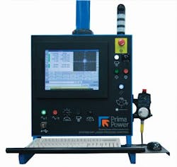
The main component of Smart Processing Techniques is the LASERDYNE S94P control (FIGURE 1) designed exclusively for high-speed, multi-axis laser processing.
The LASERDYNE S94P control includes a full complement of standard hardware and software features for integrated control of the laser, motion, process gases, and process sensors to produce smart solutions for cutting, welding, and drilling of clean, accurately produced parts. Some of the original features of the S94P include:
- Automatic Focus Control for capacitive part sensing (uncoated material);
- Optical Focus Control (OFC; patented) for sensing of thermal barrier coated surfaces;
- Breakthrough Detection software for programming shaped holes and for drilling clean consistent holes with the minimum number of pulses;
- Mapping; and
- Airflow measurement.
It also includes any other software and hardware features for precision 3D laser processing too numerous to be mentioned here.
SmartPierce
Laser piercing is used to generate a starting point for laser cutting. Traditional methods of piercing consist of peck piercing and rapid piercing. The key laser and processing parameters for piercing are pulse width, pulse frequency, peak power, duty cycle, assist gas pressure and type, nozzle standoff, and focus position. Peck piercing with maximum peak power, duty cycle, and frequency are programmed from low to upper level. The rise in duty cycle and frequency follows the progression of piercing through the thickness of metal. This method is very time-consuming when repeated many times in the course of batch production.
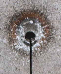
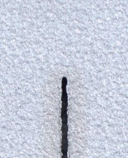
The rapid piercing method (FIGURE 2) results in a pierced hole much larger in diameter than the cut (kerf) width because the cutting is performed by continuous-wave (CW) power. With this method, excess spatter is generated and there is potential for cutting nozzle tip damage. Neither piercing method is ideal for a production environment—instead, the ideal method is the new process feature called SmartPierce, which produces a clean pierce point the same diameter as the kerf width for percussion drilling and cutting applications (FIGURE 3).
Examples of piercing with SmartPierce
Applications for SmartPierce are varied, ranging from thin to thick metal cutting and drilling. For example, in many medical device, electronics, and fine mechanics application involving small features and thin materials, features are often too small to allow for piercing in what will eventually be the drop-out or scrap. In other cases, a feature—such as a slot—is produced in a single pass without moving around the outside profile of the feature to minimize the time to produce the feature.
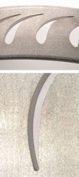
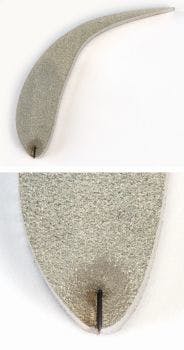
FIGURES 4 and 5 show examples of the SmartPierce technique used to produce parts that require no post-processing work and very accurate control over dimensions of the features being laser-cut.
SmartRamp
With standard laser welding practice, laser power is ramped down at the end of the weld after the start point has been overlapped. This method leaves a depression at the end point. For most applications, this depression is undesirable, but has been considered to be a "fact of life" for laser welding (FIGURE 6).
In hermetic welding, this depression at the end point can be a leak point; for applications requiring high fatigue strength, the depression represents a stress-riser for possible premature failure; and for cosmetic welds, the sight of the depression often causes quality concerns requiring additional quality control procedures.
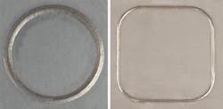
With SmartRamp, the laser parameters are controlled in conjunction with the motion so that there is no weld depression at end of the weld (FIGURE 7).
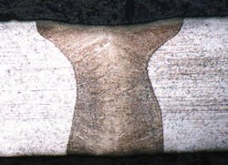
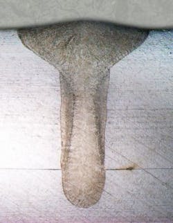
A good weld is crack- and porosity-free, and has high strength and reliability. There are a number of process parameters that affect the quality, size, and properties of laser welds. Quality welds produced with SmartRamp are characterized by reduced porosity at the end of weld and, more importantly, with more crown and less undercut of the top bead (FIGURES 8 and 9).
SmartStop
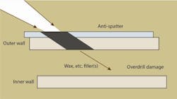
The surface behind the one being laser-drilled is referred to as the "back-wall." In turbine engine components, impingement of the laser beam on the back-wall can cause unacceptable melting of this surface. It is a common practice to use materials such as Teflon or copper sheet to form a protective barrier from the laser energy that passes through the primary surface toward the back-wall. This is marginally effective, allowing back-wall damage to occur as the laser beam penetrates the protective material. This is especially true when the back-wall is relatively close to the drilled surface. In other cases, the barrier material life may be short with inconsistent process results (FIGURE 10).
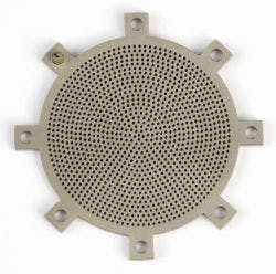
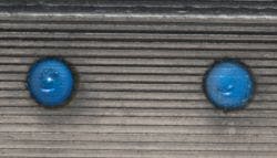
Turbine engine combustor designs often include louvers (FIGURE 11) to direct cooling air at a right angle to the surface to more effectively cool the surface. Preventing back-wall damage is challenging when laser drilling these combustors.
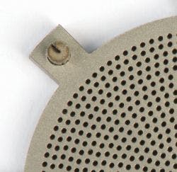
SmartStop makes it possible to avoid back-wall damage even in parts with small, 1mm gaps between the back-wall and drilled surface. Note that protection material continues to be used, though the laser control consistently prevents penetration of the material by the laser beam and extends the useful life of the material (FIGURE 12).
LASERDYNE S94P control of a fiber laser ensures that laser parameters are consistently changed quickly. Results using the recently developed SmartStop provide throughput of 1.0 to 1.5s per hole. Also, LASERDYNE's Optical Focus Control (OFC) ensures precise location of holes, whether they are perpendicular or at angles to the surface. OFC is especially useful when there is another surface near that being drilled since it is not subject to side sensing that is characteristic of capacitance-based height sensors.
Summary
The LASERDYNE S94P software developments provide new and more effective ways to control laser energy and material interaction. They provide better control to minimize and eliminate secondary processing defects during laser material processing. These SmartTechniques are:
- SmartPierce, which minimizes spatter formation during laser cutting/drilling and the diameter of the pierce point;
- SmartRamp, which eliminates weld indentation at the end of the weld; and
- SmartStop, which reduces back-wall damage during laser drilling.
The goal of developing SmartTechniques was commercially driven—that is, by OEMs seeking a total solution in terms of processing parameters and machine features (hardware and software) for processing production parts requiring no post-processing work.
ACKNOWLEDGEMENTS
Automatic Focus Control, Breakthrough Detection, SmartPierce, SmartRamp, SmartStop, and SmartTechniques are trademarks of Prima Power Laserdyne, and Teflon is a registered trademark of DuPont.
REFERENCE
1. T. J. Rockstroh, D. Scheidt, and C. Ash, "Advances in laser drilling of turbine airfoils," Industrial Laser Solutions (Aug. 2002).
Dr.MOHAMMED NAEEM([email protected]) is senior manager, business development at Prima Power Laserdyne, Champlin, MN, www.primapower.com.

