Direct measurement of laser weld depth with inline coherent imaging
Technique measures actual depth of penetration of all welds
MATTHEW B. MARSH and PAUL J. L. WEBSTER
Laser welding has become an important tool in many industrial manufacturing processes. However, assessing weld quality remains a large problem for many users.
Up until now, the available in-process sensors have used indirect measurement techniques (process emissions, plasma, etc.) that need to be trained on a specific machine through comparison with laborious destructive testing. However, they do not provide a direct measurement of weld penetration depth, one of the key indicators of weld quality. The relationship between anomalous readings and quality defects is often unclear, creating tension between quality and production interests and the respective engineers and operators. Too often, this results in indirect quality sensors being underused—or sometimes disabled altogether—resulting in wasted capital and a potentially large quality control risk.
In early 2013, Laser Depth Dynamics (LDD) began selling a new in-process quality monitoring and control technology that is able to directly measure weld penetration depth using a principle known as inline coherent imaging (ICI). Adapted from established medical imaging technology, ICI adds a low-power, near-infrared measurement beam to existing laser head camera ports. The ICI beam follows the process beam quasi-coaxially into the welding keyhole to directly measure penetration depth with high precision (~20µm) and high speed (>200kHz). Perhaps the most powerful aspect of ICI is that the measurements are not affected by the high-power laser or plasma. Thus, the keyhole depth can be measured in real time during the welding process.
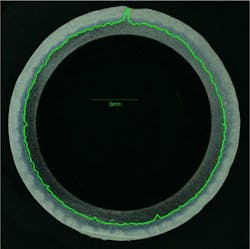
The principle has been proven and published in peer-reviewed journals [1, 2] and was first deployed in 24/7 industrial use by LDD in 2014. We have continued to innovate with the recent release of our new three-dimensional (3D) module that, along with weld depth measurement, also provides seam tracking, height following, and 3D volume imaging in a single tool (FIGURE 1).
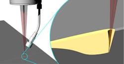
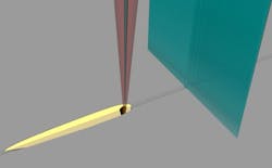
The ICI imaging beam, a low-power beam in the 800–900 nm NIR band, is combined coaxially with the process beam at the head's camera port. This beam follows the process beam into the weld keyhole (FIGURE 2). Some of this reflected imaging light is returned to the ICI system, which combines it with light from a reference path to create an interference pattern. From this interference pattern, the system can measure the distance to every surface in the imaging range that yields a reflection. If the imaging beam is aligned to the keyhole bottom, the ICI image yields a direct measurement of the keyhole depth.
ICI vs. destructive sectioning: Lap welds
The established gold standard for weld depth measurement is to cut through the finished weld, grind and polish the cut face, and then chemically etch it to reveal the grain structure. For any new quality monitoring technology to be taken seriously, its in-process results must reliably concur with the metallurgy lab's destructive sectioning results.
FIGURES 3 and 4 show ICI depth tracking traces, as observed with a Laser Depth Dynamics LD-600 system, registered to independently scale-calibrated micrographs of the longitudinally sectioned welds. The ICI depth tracking signal closely follows the true weld bottom, even including small transient defects. The accuracy of longitudinal section comparisons like these is limited not by the ICI measurement, but rather by the metallurgist's ability to cut, grind, and polish the sample to the exact centerline of the weld.
ICI vs. destructive sectioning: Spot welds
Spot welding process times are typically on the scale of milliseconds, allowing approximately 1000 ICI measurements to be acquired during a single pulse of the spot welding beam. An ICI system can therefore watch the entire formation of the weld, from the initial surface melting, through the formation and growth of the keyhole, to the keyhole collapse at beam-off and the subsequent cooling of the melt pool. The maximum depth achieved by the keyhole is the final depth of the spot weld, and this depth is easily obtained by ICI. Moreover, the intermediate measurements can be used to compare the welding dynamics to previously known-good samples. Such comparisons may be used to elucidate some subtle changes to cover gas flow and material fit-up, giving the user an opportunity to diagnose and pause critical processes before many defective parts are made and guide rework. These capabilities may be of particular interest in the medical device field: a permanent diagnostic record for every spot in every seam.
In FIGURE 5, two such spot welds are shown in acid-etched section view; excellent agreement between the ICI measured depth and the sectioned depth was found.
Automatically detecting failures
Welding quality control is a natural application for this technology. Quality control criteria can be assigned directly from engineering tolerances, in terms of a target depth range and a set of parameters describing allowable excursions outside that range.
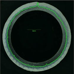
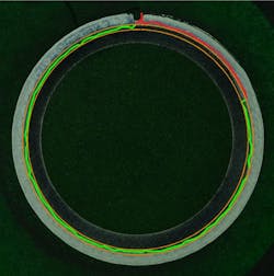
The geometry need not be restricted to simple planar geometry. FIGURE 6, for example, illustrates the radial lap welding of a stainless steel tube onto a machined boss, the entire part being held in a constant-velocity rotary chuck.
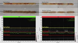
ICI can also be used in full-penetration welding. Butt welding applications, for example, often require that full penetration be achieved for the full length of every weld. Too much power, though, is wasteful and can cause molten metal to be ejected out the back side. Real-time ICI monitoring of the penetration depth, combined with automated QC analysis, can be used to generate an immediate pass/fail signal at the end of every weld (FIGURE 7). This helps to ensure the use of just enough power—but not much more—for the task, while immediately catching and rejecting any parts that do fail.
The rotary weld example in FIGURE 8 exhibits poor penetration near the end of the weld. This loss of penetration—probably caused, in this case, by runout in the rotary fixture causing the part to move out of focus—is difficult, if not impossible, to identify by visual inspection of the finished part. It is, however, immediately evident in the ICI depth trace, allowing an automated "FAIL" decision to be made.
All of this is achievable with a single instrument. Real-time quality control on every single weld, based on direct measurements of the actual depth of weld penetration, is now realistic.
3D live viewing: Beyond the inline camera
An inline camera, looking through the laser head optics to provide a "beam's eye view" of the processing region, is a useful tool for many setup and alignment tasks. It is, however, limited in its capabilities. Inline cameras acquire only 2D images, and are easily blinded by the process beam and by the white-hot glow during welding.
ICI is effectively immune to such blinding. An ICI system connected through a 3D head interface can not only acquire flat images similar to those of an inline camera, but can also provide depth profile information. This real-time 3D imaging opens up a wealth of capabilities.
Before and during a welding or ablation process, 3D ICI can be used to simultaneously confirm position, focus, and part movement. After processing, 3D ICI can produce profiles of the finished surface. Even the weld keyhole itself can be imaged in this way, providing unprecedented insight into the dynamics of the keyhole and the surrounding melt pool.
Seam tracking and autofocus
3D ICI imaging naturally lends itself to automated tracking and height following based on real-time image analysis (FIGURE 9). ICI yields excellent results in geometries that create problems for traditional structured light measurement or capacitive height sensing techniques. Due to its immunity to interference, it can take these measurements very close to the weld point.
Importantly, this tracking is done through the existing lens, with no struts or booms hanging down to support tracking sensors. This greatly increases the range of compatible part geometries. In addition, the tracking is completely optical, with no dependence on the electrical properties of the material. One system can provide height following and seam tracking on steel, aluminum, carbon composite, acrylic, and many other materials.
Conclusion
Laser technology offers the promise of high-performance, high-throughput welding at a low per-part cost. These advantages can be lost, however, if thousands of parts must be discarded because of suspected defects—or, worse, if defective parts can slip through QC and end up in the hands of customers.
Inline coherent imaging now provides a solution: a direct, independent, real-time measurement of the actual depth of penetration of each and every weld. For years, engineers and plant managers have wondered how to bring clarity and certainty to the complex, hidden processes that occur where the beam meets metal. Now, with ICI, a tool is available to answer these questions.
ACKNOWLEDGEMENTS
We acknowledge and appreciate the support of Dan Buckley and Scott Swartzinski from Laser Mechanisms, and Geoff Shannon and Wes Buckley from Amada Miyachi America.
REFERENCES
1. J. J. Blecher et al., Sci. Technol. Weld. Joi., 19, 7, 560–564 (Oct. 2014).
2. P. J. L. Webster et al., Opt. Lett., 39, 6217–6220 (2014).
PAUL J. L. WEBSTER, Ph.D., is CTO and MATTHEW B. MARSH, P.Eng, MASc, is instrumentation engineer, both at Laser Depth Dynamics, Kingston, ON, Canada; www.laserdepth.com.
