Laser marking for unique identification
Scott Davis, Elizabeth Gounaris, Susan Coffey, Kantius Joshua, Paul Denney, and Terri A. Marsico
For the DoD’s new Unique ID project, which identifies and tracks tangible assets, researchers had to ensure a readable, durable mark that does not result in fatigue-debit
In 2005, the Laser Applications Laboratory (LAL) at the Connecticut Center for Advanced Technology (CCAT) was approached by two aerospace original equipment manufacturers (OEMs) to assist in laser marking process development and optimization for use on several alloys in support of meeting the Department of Defense Unique ID (UID) initiative as outlined in MIL-STD-130 (revision N).1 A review of this document identifies three types of laser marking techniques that will meet the standard.
Basically, UID is a new method, established by the DoD, to identify and track tangible assets through their lifecycles. Tangible assets are those with >$5K value, those that are sensitive/classified, or those that are furnished to third parties regardless of their value. Such records also provide for improved operational efficiency and visibility as well as for more detailed financial management. Additional information can be found in the DoD UID Guide.2
Acceptable DoD UID part marking techniques must be identified this year and implemented by the end of 2010. To date, the laser marking techniques developed by the CCAT LAL are primarily aimed to be used on engine parts for two military aircraft, the F119 and the F100, as these have the greatest immediate need.
Direct part marking
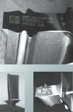
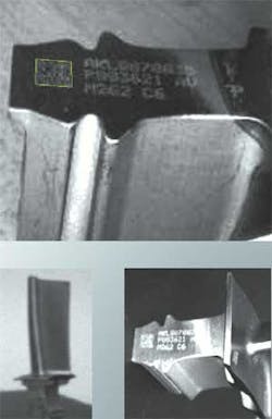
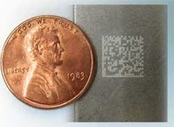
Direct part marking (DPM) is often used when, for functionality reasons, a label can not be applied or as a matter of convenience. There are several processes that meet MIL-STD-130 and are available for DPM including laser, dot peen, and electrolytic etching. Some of the advantages of using lasers over the other two methods are: no hazardous waste, no consumables, ease of use, high marking speeds, and the ability to precisely and consistently control parameters. However, there are other considerations when selecting the DPM method such as its potentially negative impact on material properties. Mark durability is also a major concern, as the mark must last for the life of the component, which may include survival in harsh environments. Marking of legacy components presents a special challenge because the original design may not have accounted for the potential associated “damage” resulting from the part marking method chosen. Examples of UID marks are shown in Figures 1 and 2.
For laser marking to meet the standards on aerospace components, the challenge is to produce robust reproducible parameter work envelopes that enable the mark to be readable and durable but do not result in a fatigue-debit to the material. Capital and process cost effectiveness and timeliness to implementation must also be taken into consideration.
The LAL evaluated products from 15 different laser marking manufacturers, and then selected and procured three laser marking systems. The selection was primarily based on cost, ease of use, and the expected ability to mark a wide range of materials including difficult-to-mark materials. Lasers selected were: an Yb:glass fiber laser, a CO2 laser, and a Nd:YVO4 system. Aluminum 7075-T6 was the first alloy selected for process development, optimization, and qualification because of OEM interest and the large existing OEM mechanical property database available for subsequent comparison to post-processed material. Other materials being studied are Ni-based alloys, Fe-based alloys, Ti-based alloys, and ceramic matrix composites (CMCs). The longer term goal of the CCAT UID laser marking program is to develop and implement a methodical systematic approach to identify and optimize laser direct part marking for robust and consistent parameter work envelopes so that these can be used in manufacturing environments to meet the MIL standard requirements and materials mission criteria, that is, a laser part marking database available to OEMs and suppliers.
The first phase of laser DPM process development focused on determining the impact of individual and combined process parameters on the mark depth and resultant material fatigue properties. Initial tests revealed that the CO2 laser, probably due to its longer 10.6µm wavelength, and relatively low output power, 10W, was inadequate for producing marks deep enough to be read and verified. Subsequent process development was performed using the Yb:glass fiber and Nd:YVO4 laser systems, respectively.
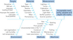
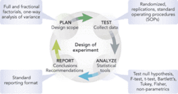
Because of the number of individual process parameters to consider, as shown in Figure 3, a design of experiments (DOE) approach was implemented and is summarized in Figure 4; a round of tests typically consisted of about 600 marks. Position of focus, output power, marking speed, and laser pulse duration and pulse frequency were varied. The results of the DOEs were graded from Passed to Not Passed, primarily based on meeting the key process outputs of mark depth below the threshold where mechanical property debit would occur; mark readability; and mark quality (the ability to verify and validate the data). Several rounds of DOEs were required to begin to identify acceptable working envelopes for each laser system. Experimentation is on-going.
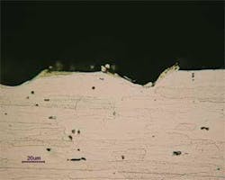
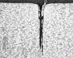
Legacy mechanical property data was reviewed in order to determine a maximum acceptable mark depth corresponding to the material’s damage tolerance threshold. The fatigue effects from laser marking were determined by producing marks at known depths and performing subsequent tests. To date, fatigue testing indicates that laser marks behave as pure fatigue cracks equivalent to the laser mark depth, including the heat affected zone, meaning that fatigue debit will increase with increasing laser mark depth; the details of the mechanical property study and the use of laser generated crack-like features for materials validation were presented and published recently.3 A cross section of a laser mark is shown in Figure 5 and that of a laser generated crack-like feature is shown in Figure 6. In addition, standard metallographic and reflected light microscopy techniques4 were used to determine the extent of the formation of any heat affected zones that were found to be dependent upon the selection of laser system and parameters. DPM durability was determined by use of a standard Tabor test; results were found to be acceptable.5
Related and future work
In the case of some materials, contrastndash;the ability of the mark to be read and verifiedndash;as a result of laser marking is not always adequate, for example sometimes on aluminum alloys. The LAL has performed laser marking trials on 7075-T6 aluminum using both DPM and the Cermark additive process techniques. Cermark is a ceramic that is added to the process if or when readability is not sufficient. Test specimens were produced and mechanical tests were performed. Based on results received to date, the depth of the laser mark appears to be the only factor that impacts the fatigue limit of the material.
The Cermark process results in increased durability, based on the Tabor abrasion test, when compared to shallow (0.00025 in. deep) DPMs; both displayed similar fatigue limits. The durability of a deep (0.001 in.) laser mark was similar to that of the Cermark process based on the Tabor abrasion, but the deep laser mark showed a fatigue debit. The Cermark additive process is used to provide a higher contrast readable mark, but it involves extra operations that may not be desirable in production because of added process cost.
Planned future studies toward the optimization and qualification of direct part marked 7075-T6 aluminum on both laser systems using DOE will produce a methodology that will then be applied to select Ni-based, Ti-based, and Fe-based alloys and CMCs. Eventually, the DOEs will incorporate approaches aimed at the laser physics relationships rather than on individual process parameters, and laser marking guidelines will be generated.
Acknowledgments
The LAL Team would like to acknowledge and thank CCAT and its National Center for Aerospace Leadership (NCAL) for its funding via the National Aerospace Leadership Initiative (NALI).
The authors are all with the Connecticut Center for Advanced Technology (CCAT), East Hartford, CT; www.ccat.us.
References
- MIL-STD-130N Department of Defense Standard Practice Identification of US Military Property, US Department of Defense, December 17, 2007.
- DoD UID Guide, Department of Defense Guide to Uniquely Identifying Items, Office of the Deputy Under Secretary of Defense (Acquisition, Technology & Logistics), Version 1.6, June 1, 2006.
- Aaron Nardi, Stephen L. Smith, “Laser Generated Crack-Like Features Developed for Engineering Assessment of Fatigue Threshold Behavior in 7075 Aluminum,” presented at the 36th ASTM National Symposium on Fatigue and Fracture Mechanics sponsored by ASTM Committee E08, November 14-16, 2007, Tampa, FL USA.
- “Standard Methods of Preparation of Metallographic Specimens Standard for Metallography,” ASTM E 3-80.
- “Tabor (Abrasion) Test,” ASTM D-1044.
