Competing in the Laser Cutting Market
Glenn Binder
Integrated CAD/CAM is the key to globally competitive laser cutting productivity
Because of increased domestic competition and globalization, North American manufacturing companies are facing escalating pressures to increase productivity. To counter this in 2D cutting applications, manufacturers, steel service centers, and job shops are investing in speedy and accurate laser cutting machines. These machines come with high price tags that place additional pressure on the laser cutting shop to compete and to have a positive return on the machine investment.
Investing in the laser machine enables these companies to compete; however, it is only a partial solution. Another vital part is the CAD/CAM software program needed to drive the machine. Efficient nesting, motion control, and programming is just as important. The software controls all the machine motion and hinders output if not used properly. Therefore one can conclude that it is the combination of both the machine and CAD/CAM software that addresses the cutting productivity needs for laser cutting. Or is it?
Success in maximizing laser machine cutting efficiency often leads to bottlenecks in material-handling or production scheduling systems. Therefore it might be that integrating CAD/CAM softwarendash;which increases decision-making visibility and reduces non-value-adding activities, leading to increased laser on-timendash;has become the next challenge. It is only if these three factors are employed and continuously improved will the laser cutting shop be truly competitive globally.
Laser cutting vs. other processes
Competing processes include oxyfuel, plasma, and waterjet cutting on thicker materials and punching on sheet metal and other thinner materials. Consider the following framework for laser plate cutting.
Oxyfuel has a long history as a process for cutting steel plates. Thicknesses up to 12in. are possible and sometimes exceeded. Laser plate cutting on the other hand is typically limited to around 1.25in. for a 6kW machine. Oxyfuel cutting lends itself toward multi-torch cutting at very little incremental cost, while laser, waterjet, and plasma machines with multi-cutting heads have higher extra costs, which include adding pumps and generators. The heat affected zone (HAZ) with oxyfuel and plasma cutting can be excessive and the accuracies are lower than that for laser cutting. Some recent innovations with plasma cutting nozzles and processes have produced improved accuracy and quality edge finish. The laser has given manufacturing another tool because of the extremely localized nature of the molten metal zone generated during cutting.
Although it too is a thermal process, the actual area heated by the laser is very small and most of this heated material is removed during the cutting process. Thus the HAZ is minimized compared to other processes such as plasma and oxyfuel cutting. The kerf width is extremely narrow (typically 0.1 to 1.0mm) and therefore detailed work can be carried out without the restrictions of other mechanical processes like milling. It is also a noncontact process so the lack of mechanical force on the sheet being cut allows parts to be arranged in a nest very close together. The laser cuts at high speed: for example, 2mm thick mild steel at 6 m/min and 5mm thick acrylic sheet at 12m/min.
Competitive punching processes have been traditionally used for producing precision holes, with recent advances enabling them to punch, nibble, and form sheet metal while maintaining high precision. Nibbling refers to separating a part bit by bit along any formed cutting line by punching several individual overlapping holes. The punch machine can produce other work processes like forming and extrusions, beads and louvers, which, for instance, are required in the manufacture of electrical cabinets.
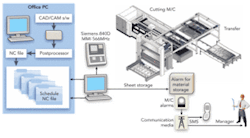
FIGURE 2. Full integration schematic.
Some punching machines can run at 1000 strokes/min. A nibbling tool can move at 4000in./min., which is substantially faster than a laser. For example a laser would cut 10 gauge mild steel at around 150in./min. Set-up times, which include placing of punches and dies and programming, are longer than those used in laser cutting, so there is a trade-off. Today the flexibility of laser programming and quick set-ups make it a better choice for producing sheet metal products in the industry.
Laser CAD/CAM system
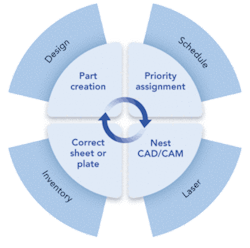
The second important factor is choosing good CAD/CAM programming software to combine with the laser machine. The software process of producing parts on a laser is a system with an input, a process, an output, and then a feedback loop.
FIGURE 3. Example of a material tower with a loader.
There are two main forms of input. One, always required, is the geometry or drawing of the part; the other is the demand data for the part, which is typically the quantity required, due date, material type, and thickness.
The geometry input comes from CAD, which has many formats such as .DXF, .DWG, and .IGES.
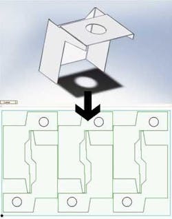
Currently solid modeling has grown in functionality, and with price reductions it has become common in industry. Solid CAD systems allow the designer to visualize the product in 3D, making it easy to conceptualize. The challenge has been how to communicate the design to the CAM system to produce parts. In the machining field, CAM has been successfully used to produce part forms or shapes by milling and turning. In the laser field, this has been neglected until recently and 3D CAD parts are now able to be unfolded if necessary and exported into the CAM system ready for programming. Bend allowances are calculated by the Solid CAD system.
Nesting technology
Nesting includes the laying out of either multiples of the same part or a series of different parts of the same material specification on a plate or sheet. There are financial and organizational benefits for applying nesting techniques, which may be manual, automatic, or a combination of both. The minimization of wastendash;being a core driver these days in productionndash;is addressed through the nesting system by optimizing the material used and minimizing production time.
Different kinds of nesting programs are available and vary in complexity. The simplest nesting programs construct a circumscribing rectangle around each component. If the components themselves are rectangular, this system will be adequate. If, however, the parts have more complex geometry or have large internal openings, then a more sophisticated nesting system is needed that uses the actual border of the part to create the nest. This greatly improves material utilization when producing these more complex non-rectangular parts. During placement sheet/plate length and width, part clearance, and edge distance need to be considered. In the laser process, this is normally constrained by the thickness of the material.
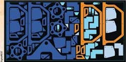
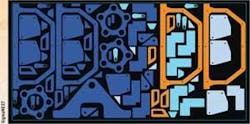
The goal of a nesting strategy should be to place the parts in an economical fashion using the highest level of automation to maximize the utilization of the sheet or plate, producing as little scrap as possible. Because of an almost infinite number of possible permutations and combinations, nesting is not an exact science. Therefore there is an iterative strategy to give the best nest result within the time constraint available. An example of a “True Shape” nest is shown in Figure 1.
Once the nest has been completed and accepted, the cutting sequence needs to be programmed. This may be achieved either manually, automatically, or a combination of both. The main objective is to minimize the head travel to optimize the process. Various routines drawn from operations research techniques are employed. Thermal effects are also considered. Although the laser process minimizes generated heat, the head may be moved to different areas of the sheet or plate to equalize the thermal effects. Other movement routines like “left to right” or “bottom to top” may be desired. There are three basic moves: rapid, cut, and pierce. Rapid moves involve moving from part to part without cutting and may be carried out with the head up or down.
Piercing, although a necessary component to initiate a cutting process, may be minimized to reduce overall production time and wear and tear on consumables such as nozzles. For example a pierce routine on 12.7mm mild steel plates could take around 0.7s with 100 pierces taking more than a minute of production time. The three main pierce reduction routines that address this challenge are common line cutting, bridge cutting, and chain cutting.
Once the G-code has been produced, the operator needs to know which parts have to be produced on what sheet or plate. This is achieved in the CAD/CAM system by the production of reports that act as instructions and guide the operator in sheet or plate selection, graphic representation of the nests, and estimated cutting times. These reports may take on various formats depending on the laser cutting shop. Once the parts have been produced, there needs to be a system that allows for feedback to the input/order side to complete the loop.
Quality requirements are more critical in today’s laser cutting processes. Edge finish and geometric criteria of parts have to be met in order to be accepted. Modern CAD/CAM software has the ability to “update” the system with the integrity of the cut parts. Once parts are cut, there might be reason to reject certain parts based on the quality criteria. This implies that the parts need to be either reworked or re-cut. If parts need to be re-cut, then the CAD/CAM system needs to feedback that demand back into the input stage. This completes the loop.
Integration
Although much work goes into the science of laser cutting as well as many algorithms and functions in CAD/CAM nesting, the major portion of manufacturing time is wasted in setting up the machine, waiting for material, and other non-value-adding activities, which can typically amount to ~90% of total manufacturing lead time defined as time from placement of order to the receipt of the goods. Manufacturers have used material requirements planning (MRP) and enterprise requirements planning (ERP) systems to improve company operations. Many of the Toyota production systems, techniques like the Kanban bin system and the Kaisen continuous improvement systems, have also been employed. More recently the whole discipline of Lean Manufacturing has been initiated in many shops.
Figure 2 shows how this applies to the vertical connection to these and similar systems. In this case, the demand for laser-cut parts is seamlessly transferred to the programming system through the creation of work orders. Data transferred is typically, but not limited to, part number, order number, order quantity, and due date. The programmer therefore has all the information required to make a nesting decision based on the presented criteria.
The other important integration factor is inventory control. Shortage of material and long load/unload times is another major element preventing shops from becoming world class competitors. Fortunately, OEMs have developed a number of material handling systems and there are a number of material towers and load/unload systems available. An example may be seen in Figure 3, where material sheets are placed in a material storage tower normally in drawers of around 8 to 10 per tower. The inventory of each station is monitored and sheets are removed one by one and transported and placed on the laser machine cutting table. Once the cutting process has been completed, the parts and skeleton are removed, ready for the next downstream process. The next sheet is presented to the machine ready for cutting. Many shops are using these systems to operate in a “lights out” mode.
The final level of integration that allows shops to become globally competitive is the integration to solid CAD engineering design packages. Solid modeling design of parts and assemblies has been a growing trend and vendors are making it simpler and easier to use, along with the need for design for manufacturing (DFM). The need to easily access a sheet metal part or assembly, bring it into the CAM nesting software, and efficiently produce programs has been addressed, an example of which may be seen in Figure 4.
Conclusion
Companies are investing in laser cutting machines and CAD/CAM nesting and programming software. There has been a realization that the laser machine and the CAD/CAM nesting software alone are not enough to catapult the company into true global competition. Integration into the company systems has become the next enabler.
Three main integration paths have been discussed: integrating into MRP/ERP systems where customer demand is managed; integrating into Solid CAD parts or assemblies; and managing inventory and material handling systems.
If integration combined with good CAD/CAM nesting systems and efficient laser cutting machines are taken into consideration and employed, laser cutting shops can be truly competitive in the global community.
Glenn Binder ([email protected]) is VP of sales for SigmaTek Systems, Cincinnati, OH, www.sigmanest.com.
