Paving the way
KENT INOUE
Slip and fall accidents on wet, slippery surfaces may sometimes develop into serious court cases, and many building owners are very aware of this problem as a major source of risk. Conventional antislip measures include stone surface treatment using a gas burner, application of antislip tapes, and stickers, each of which has various disadvantages in cost, cosmetic appearance, and maintenance. Gas burner treatment deprives the stone surface of its luster and its unique aesthetic properties, while antislip tapes are highly susceptible to wear and tear and require maintenance or replacement about every six months, which adds cost.
Considering the shortfalls of conventional antislip measures, Taisei, a major construction company in Japan, in conjunction with Kantum Electronics, has eveloped a new pavement/stone treatment process using carbon dioxide (CO2) lasers. The “Non-slip Safety Groover,” a pavement-grooving machine for antislip safety treatment, paves the way for new applications of CO2 lasers.
Choice of laser
During the design phase of the groover, Taisei selected a CO2 laser because of its beam interaction with masonry stone. The company discovered that light from CO2 lasers with a 10.6-μm wavelength is better absorbed by stone compared with light from other types of lasers, such as semiconductor and Nd:YAG lasers. In the interest of processing speed, the higher the laser output the better. However, the equipment must be compatible with outdoor use, and this prerequisite consequently narrows down the available options.
“As the equipment was intended for outdoor use, we decided to build air-cooled systems, not water-cooled,” said Masashi Yoshitome, manager of marketing and sales at Kantum Electronics. “A water-cooled system could cause problems such as hose dislocation, which we wanted to avoid as much as possible.” Yoshitome also said that the equipment must be light enough for portable use. “Therefore, we concluded that 100W air-cooled CO2 lasers were the best possible option.” The first prototype of the groover was built in 2003 with a 100W air-cooled CO2 laser supplied by Synrad.
Reliability is key
The prototype consisted of two boxes, the grooving machine unit and the power supply unit, which were interconnected by a cable. The equipment operated on 100 Vac, which is the standard line power most readily available through wall plugs in Japan. Despite the heavy weight (the 100-kg grooving machine plus the 70-kg power supply unit), the equipment was highly mobile thanks to the wheels provided.
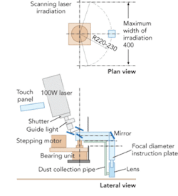
The grooving machine was equipped with a laser head that moved via an x-y stage that is controlled by proprietary software for engraving different 2D patterns such as grids and swirls. To gather data and information necessary for identifying problems with the first prototype and for developing the second, Taisei installed antislip grooves to the pavement and floor tiles at several public places, such as Japan Railway’s Oimachi Station in Tokyo and Karuizawa Station in Nagano Prefecture railway stations, using this prototype.
The test demonstrated that the prototype had sufficient reliability and durability. Despite the tough environmental working conditions (outdoors with a high level of vibration and dust), the CO2 laser performed very well. Even after a total of 2000 working hours (including test runs at Taisei’s lab), the equipment did not experience any laser problems or output failures.
Second prototype
Taisei then began development of the second prototype, the improved version, together with Kantum Electronics, that was completed in April 2007. Major changes have been made to the second prototype. The weight and width of the equipment have been reduced to make carrying and handling easier. Therefore, the number of engraving patterns had to be compromised as a necessary trade-off.
“The first prototype could engrave a variety of patterns such as grids and swirls as it was equipped with an x-y stage, which in turn added extra size and weight to the unit,” said Yoshitome. “We have therefore decided to cut down the variety of grooving patterns to only one-a circular arc. We made this compromise because we had other priorities. Minimization of the size and weight was the main objective of the second prototype.”
As a result, the machining unit weight was reduced from 100 to 65 kg. This eliminated the need for a special vehicle with a lift, which had to be used to carry the first prototype to the work sites. Thanks to the reduced width, the new prototype was also able to pass through the ticket gates with ease, unlike its bulky predecessor.
The current downsizing has also minimized the “dead space,” a space the grooving head could not reach to cut the pavement/stone tiles. The first prototype had dead space as large as 100 mm on the both sides and at the front. This side and front dead space was reduced to 40 mm and 45 mm, respectively. The track width is normally set at 400 mm to match the size of a standard stone tile (400 x 400 mm). This means that the new prototype can reach further into the corners, leaving only a small untreated dead space (1/10 of the track width) on both sides and at the front of the equipment.
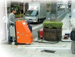
The grooving machine automatically slides along the preinstalled guide rail, moving in a circular motion within the preset track width of 400 mm. Unlike the fully manually operated prototype, the advanced version enables almost unmanned operation. All the operator needs to do is stand by and monitor the equipment with the remote controller in hand to ensure safety (see Fig. 1). The second prototype equipment also includes additional new features such as a power checker and a dust collector. The connection cables have been reinforced for heavy-duty use.Further efficiency
The handling, workability, and operating efficiency have already been improved to a reasonably sufficient level for the second prototype of the groover. Satisfied, but not complacent, however, Taisei and Kantum Electronics are determined to pursue further refinement of the equipment to make it even more efficient and compact.
Yoshitome says current work includes the development of an original high-output system in which two air-cooled 100W laser units are merged with a beam combiner to deliver an output of 200 W. The development team also believes there is room for further downsizing by modifying the sheet-metal thickness and the body material itself. To improve workability, the full utilization of sensors is being considered to achieve greater levels of automation. Development of this higher-output, lower-weight equipment implies an additional investment cost, but also leads to improved tact time and eventually to reduced operating cost.
The second prototype of nonslip safety groover was presented at InterOpto’07 in July 2007 and interested many visitors, including a building maintenance company owned by one of Taisei’s competitors. This high level of attention has revealed how much building owners are concerned about the potential risk of slip and fall accidents on wet days.
Postconstruction antislip safety treatment using pavement grooving machines like this groover have been conducted only in the Kanto area (Tokyo and six neighboring prefectures) so far, and Taisei and other operators are considering rolling it out to all of Japan in the future.
Kent Inoue is a contributing editor for Industrial Laser Solutions Japan. Contact him at [email protected].

