Laser welding automobile bumpers
M. J. Song, B. H. Jung, M. Y. Lee, and J. Suh
Remote welding system with shielding gas welds auto parts efficiently
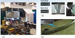
Using a remote welding system (RWS) with a high-power CO2 laser and scanner increases welding cycle time over using a more conventional fiber-delivered laser/robot system. Because the CO2 laser RWS has a beam focal length in excess of 800 mm from the workpiece, it is possible to reduce the welding cycle time because the mirrors of the scanner system allow positioning speeds in excess of 700 m/min (see Fig. 1). Also, the RWS has a sensor to automatically measure focal length from the workpiece, making it easy to change and check welding patterns and positioning data.
However, with a RWS, there is no provision for applying shielding gas, which is normally required when CO2 laser beam powers exceed 3 kW, and implementation of such a shield gas system becomes difficult. So, in a recent study, 800-Mpa class high-tensile steel sheets were welded by RWS to observe the factors influencing bead shape and penetration in response to using or not using shielding gas. Also studied were the parameters that have an effect on tensile load on auto components.
Researching optimum conditions
In the study, SPFC 780 1.2-mm-thick steel plates were welded. The applied laser power was 3–4.8 kW at travel speeds of 2.4, 2.8, and 3.2 m/min to allow observation of the shape of fusion zone influence by plasma with and without shielding gas. A stitch weld 22 mm long was produced, with a flow rate of helium shielding gas at about 25 l/min. This gas was delivered from a circular jet orifice (see Fig. 2).
The higher the applied power, the more different the fusion zone shape, depending on the existence of shielding gas or not. As the process became unstable, owing to the absence of shielding gas, the penetration at higher beam power was considerably less. The interesting fact is that the weld width increased at higher welding speed in compliance with that of full penetration. The table shows the shape of the bead and penetration with and without shielding gas at 4.8 kW.
During the process, the RWS was more seriously affected by atmosphere than other types of laser systems because of the long focal length of CO2 lasers, so the calculated area of each section had to be observed to obtain precise data for fusion shape (see Fig. 4). When each section was reviewed, there was a variation of penetration and welding width during the process. So, we found that shielding gas has an effect on penetration and weld width and that it stabilizes the process.
On the whole, the peak tensile values were observed at 2.8 m/min with the exception of some conditions; we conclude that tensile load for overlap welding does not have a great deal to do with penetration. Because of the lower welding speed, better penetration was generally obtained. Tensile load may not be directly proportional to penetration weld width (see Fig. 5). For more precise data, the area of fusion was compared instead of the weld width. The welding condition that takes advantage of tensile load is to extend the weld width.
Even though the absence of shielding gas produced slightly higher tensile load values, shielding gas was essential in the process when using 4.8kW laser beam power. In this case, unless shielding gas is supplied, the process becomes unstable, and penetration values are too low (see Fig. 6).
The RWS welding process described here has been used since 2006 to weld automobile bumpers (see Fig. 7). Normally bumpers are welded using resistance spot welding, CO2 arc welding, or cold metal transfer welding. The laser was selected because it offered reduced cycle times, reduced material cost, and improved tensile load values. We plan to study use of the RWS on other auto components.
null
Results of the study
We came to several conclusions as a result of this research. First, shielding gas is essential in the bumper welding process at laser beam powers greater than 4.8 kW. Unless shielding gas is supplied, this process becomes unstable, and there is random bead penetration. As the steel plates (SPFC 780 1.2t) were overlap welded, the fusion shape changed from section to section. Thus, to obtain more reliable data, it is necessary to calculate the fusion zone area.
In addition, values of tensile load are generally high at middle welding speeds. So penetration does not affect the quality of overlap welds. When shielding gas was applied, the welding process at high laser beam power was extremely stable. So to obtain full penetration and stable welding quality, shielding gas is essential.
M. J. Song ([email protected]), B. H. Jung ([email protected]), and M. Y. Lee ([email protected]) are with the Technical Institute of Sungwoo Hitech, Busan, Korea, and J. Suh ([email protected]) is with the Korea Institute of Machinery & Materials, Daejeon, Korea.


