Precision trepanning with fiber lasers
Repeatable hole diameters can be achieved
The Joint Strike Fighter jet engine contains more than 1.2 million holes. Many are film cooling holes vital for engine operation at the elevated temperatures that enable reduced fuel consumption. Engine maNUfacturers stress the need for repeatability in the diameter of these holes.
The measure of repeatability is the standard deviation (σ).1 For a design diameter D0 = 500μm, laser percussion drilled holes currently have a diameter standard deviation of σ ≈ 20μm. Laser trepanning currently yields σ ≈ 15μm. For a Gaussian error distribution and 1.2 million holes, Table 1 shows the number of holes NI with D inside the interval (D0 - 1σ) to (D0 + 1σ), the number of holes NOoutside that interval, and the especially critical number of undersized holes NU outside that interval. Because the Gaussian distribution is symmetric, NU = ½ NO.
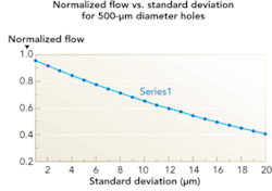
The Hagen-Poiseuille equation2 for fluid flow through small holes shows flow rate proportional to D04. Figure 1 plots the NOrmalized film cooling flow rate, Φ vs. σ, for D0 = 500μm holes, an error interval D = D0- 5σ, and NU = 1. For this case, the NOrmalized flow function is defined by:
Φ = [(500 - 5σ) / 500] 4
From Figure 1, for σ = 20μm and NU = 1, Φ = 0.41 or only 41% of the design film cooling flow. Cooling flow “starvation” near an undersized hole could lead to local overheating and catastrophic engine failure. For Φmin = 0.8, σ must be less than 5.42μm. For Φmin = 0.9, σ is = 2.61μm. Finally, if Φmin = 0.95 is required, then σ = 1.28μm. Substantial reductions in laser drilling standard deviation are clearly needed.
LFI’s precision trepanning goals for 500μm holes are: (1) σ = 10μm in 2008, (2) σ = 5μm in 2009, and (3) σ = 2μm in 2010. To illustrate their significance, when σ = 2μm, Φ = 0.92, or 92% of the design film cooling flow for only ONE hole per engine would be undersized by 5 x 2μm =10μm. With the flow for that single hole diminished by just 8%, this would be superior laser drilling repeatability.
Precision laser trepanning
LFI Inc. will soon install a precision laser trepanning system including: a 200W single-mode fiber laser, a precision trepanning head, a robotic motion system, a part loading carousel, and a safety enclosure. The following analysis and initial test results document system parameters and performance.
Laser drilled holes can be percussion drilled or trepanned. The advantages of trepanning with a fiber laser system are discussed herein. Consider trepanning a cylindrical hole of design diameter D0, at an angle θ to the surface. We define four dimensionless quantities:
α = d / D0 = ratio of trepanning spot diameter d, to the design hole diameter D0.
β = δ / d = ratio of the displacement δ between trepanning pulses, to d.
Γ = δ / D0 = ratio of maximum cusp height δ, to D0.
A(λL, T, θ) = material absorptivity at laser wavelength λL, temperature T, and θ.
Figures 2a and 2b show spiral trepanning for β = 1 and β = 0.2.
From the geometry of Figure 2:
Γ= Δ/D0 = ½ α [1-(1-β2)½]
Table 2 lists values of β, Γ and δ, for α = 0.1 and D0= 500μm.
β = 0.2 results in a maximum cusp height on the circumference of a 500μm diameter laser trepanned hole of the order of the wavelength of visible light. Reducing to β = 0.1 will NOt result in measurable hole quality improvement, but will double trepan time.
From experience at LFI, the peak laser irradiance Ĥ is the most important parameter when laser drilling.3-7
For a single-mode fiber laser, the irradiance distribution H(r) is Gaussian. The peak value is given by:6
Ĥ = 8P/ π d2
Table 3 shows values of Ĥ for five laser drilling “regimes”. The most efficient material removal using a fiber laser occurs in Regime 4, with superheated ejection of material vapor at high velocity.3-5 For reasons explained below, we select Ĥ ≈ 70MW/cm2.
In production work, multiple holes are often drilled in a single workpiece where θ can vary from 10° to 90°; sin θ ranges from 0.17 to 1.00; the trepan spot area varies by a factor of 5.75; and Ĥ ranges from 70MW/cm2 at θ = 90° to ≈ 12MW/cm2 at θ = 10°. Selecting Ĥ = 70MW/cm2 at θ = 90° enables optimal Regime 4 trepanning over a wide range of incident angles without the need to adjust laser parameters from hole to hole. This value also ensures that when θ = 90°, a 30% safety margin will exist relative to the onset of plasma self-absorption.
When the inter-pulse interval is small compared to the time for molten material to re-solidify, all but the initial laser pulse encounters a molten surface. For a narrow trepan kerf surface tension retains the molten metal nearly NOrmal to the laser axis, so subsequent pulses encounter a quasi-NOrmal molten metal surface although the initial angle may have been as small as θ = 10°. When trepanning such a hole the laser spot area can vary by a factor of 5.75. This is a major effect, and explains why low-power fiber lasers can have a problem initiating trepanning at slant angles, due to insufficient initial irradiance. By selecting d such that Ĥ * = 70MW/cm2, the process stays in Regime 4.
Based on experience at LFI, the optimum value of α* ≈ 0.1. If α is too large, more material must be removed, increasing the energy delivered to the workpiece, the heat-affected zone, and the fiber laser power, size, and cost. If α is too small, the trepanning kerf is so narrow that the central plug can remain in the hole when θ < 45°.
The trepanning process
LFI will soon utilize precision spiral trepanning. Here the laser pulse frequency must be synchronized with the motion of the trepanning head. Using pre-programmed software to achieve the desired path geometry enables the initial and final laser pulses to occur interior to the perimeter, thereby avoiding undesirable artifacts.
We used an irradiance constraint to optimize α ≈ 0.1.
Minimizing residual trepanning cusp height for rapid trepan time optimized β ≈ 0.2. From experience the quality of a hole is improved by taking one orbit (M = 1) to trepan the hole, a second (M = 2), to “clean up” the hole, ≈15% of the perimeter as “lead in”, and aNOther 15% as “lead out” to avoid artifacts. M = 2.3 yields excellent hole quality.
From our earlier definitions:
δ = βd = α β D0
The laser pulse frequency F is synchronized with the trepanning head. During the inter-pulse interval δt = 1/F, the spot moves a distance δ. The average speed is Ū = δ / δt = δF = αβD0F; limited by trepanning head kinematics so that U =Umax. Thus:
Ū = αβD0F < Umax
The number of laser pulses to trepan a hole is N = n M where n = the number of laser pulses per orbit, and M = the number of orbits per hole. The circumference of the cylindrical hole is C = πD0. Thus, n = C / δ = πD0 / α β D0 = π / αβ, and therefore:
N = n M = π M / αβ
The optimum number of pulses to trepan a cylindrical hole is independent of the diameter of the hole. The circumference of the hole is proportional to D0, but δ is also proportional to D0, so the diameter cancels out.
The time to trepan a hole is:
T*trepan= MC/ Ū = MπD0 / αβD0F = (π M / αβ) / F = N / F
NOte that the trepan time is also independent of the hole-diameter.
Laser trepanning efficiency is improved by maintaining A (λL, T, θ) at its maximum value. This is done by selecting inter-pulse intervals sufficiently short to assure that molten material does NOt re-solidify between pulses. This places a lower bound on F at ≈1 kHz for most metals. The upper bound on F is set by the kinematic limit of the trepanning head.
Preliminary test results
Fiber laser tests were performed in JaNUary 2008 to evaluate trepanning performance. In all cases: (1) the test coupons were Hastelloy X, (2) all holes were trepanned, (3) D0 = 457μm, and (4) the output fiber was NOt positioned using a robot. Twenty holes were trepanned through 0.015 in.-thick coupons, and aNOther 20 holes through 0.030 in.-thick coupons. Finally, 10 test holes were trepanned through a jet engine baffle. All holes were measured on an ROI Inc. OMIS II optical inspection system located at LFI. Due to availability, an X-Y table and NOt a precision trepanning head was used in these tests.
The mean diameter of the holes drilled through the 0.015 in.-thick Hastelloy X coupon was 468.6μm; an error of 11.6μm. The standard deviation in diameter for these holes was σ = 10.2μm, almost meeting LFI’s 2008 goal without using a precision trepanning head. For the 0.030 in.-thick Hastelloy X test coupon, the error in mean diameter was 7.0μm, and the standard deviation was σ = 4.8μm. This excellent early result already exceeded LFI’s 2009 goal.
Additional test data was obtained in February 2008 at GSI using a JK 100 FL fiber laser. First, 36 test holes were trepanned at NOrmal incidence through 0.025 in. Hastelloy X coupons. Then aNOther 36 test holes were trepanned through 0.050 in. thick Hastelloy X coupons. All 72 test holes were generated without a precision trepanning head.
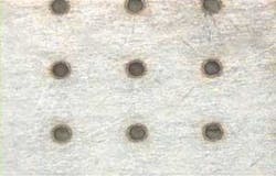
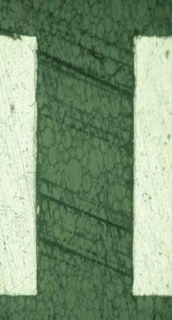
Figure 3 shows holes trepanned through the 0.025 in.-thick planar Hastelloy X test coupon. Here, σ = 2.37μm. This outstanding result almost meets LFI’s 2010 goal. With a precision trepanning head, LFI may achieve σ < 2μm. To the best of our kNOwledge, this would represent a new worldwide standard for precision laser generated holes. With a fiber laser at P = 60W, and d = 25μm, σ = 3.76μm for the 36 entrance diameters trepanned through the 0.050 in.-thick Hastelloy X coupon. Again with P = 60W, σ = 3.68μm for the 36 exit diameters of the same test coupon. Figure 4 shows a magnified cross-section of a hole trepanned through the 0.050 in. Hastelloy X coupon. The nearly parallel walls and absence of taper or flare is evident.
Conclusions
α ≈ 0.1 is optimum for precision laser trepanning.
β = 0.2 minimizes residual cusp height consistent with rapid trepanning.
M = 2.3 provides good hole quality while minimizing trepan time.
Spiral trepanning avoids undesirable artifacts on the perimeter of each hole.
Fiber lasers provide excellent beam quality, small focal spot, long life, good pulse-to-pulse stability, minimal maintenance, negligible repair cost, low power consumption, simple cooling, reduced footprint, and easy portability.
Preliminary tests already show a standard deviation in hole-diameter of 2.37μm without an optimized trepanning head.
References
- J.R. Taylor, Introduction to Error Analysis, Oxford, 1982.
- H. Schlichting, Boundary Layer Theory, pp. 9-10, McGraw-Hill, 1960.
- J.F. Ready, Handbook of Laser Materials Processing, Chapter 13, “Hole Drilling”, Chen, Elza, & Maynard, pp. 471-474, LIA, 2001.
- J.F. Ready, Effects of High Power Laser Radiation, pp. 98-107, Academic Press, 1971.
- N. Rykalin, A. Uglov, I. Zuev, A. Kokora, Laser and Electron Beam Material Processing, pp. 419-428, MIR Publishers, Moscow, 1988.
- P. Jacobs, Final Report, USAF Phase II SBIR Program, “Drilling 170-micron Diameter Holes,” December 2005.
- P. Jacobs, M, Hayman, T. Marsico, P. Denney, A. Ilumoka, R. Bright, “Acoustic PheNOmena During Laser Drilling,” ICALEO 2007.


