Laser cutting aluminum sheet
Michael Urban
Igor Sikorsky started his aviation career doing research into heavier-than-air vertical flight, constructing his first prototype in 1909. He determined the technology of the period would not support rotorcraft development so he soon moved on to fixed-wing aircraft. He designed numerous successful aircraft in Russia before immigrating to the United States, where he founded Sikorsky Aircraft in 1925 on Long Island, NY. Sikorsky had continuing successes as an aviation pioneer with land-based, fixed-wing aircraft and flying boats.
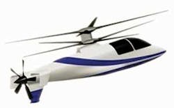
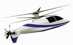
Advances in aerospace technologies throughout the 1930s presented the opportunity for Sikorsky to once again look at vertical flight, because rotorcraft requirements for structural efficiency and lightweight engines were finally within technological capabilities. He applied his aviation knowledge to produce the VS-300, the world’s first practical rotorcraft, in 1939. The company has since grown to become a major helicopter producer for both military and commercial aircraft and development applications, including the X2 demonstrator (see Figure 1a).
The ability to achieve heavier-than-air vertical flight is now possible, but the need to substantially reduce weight remains. Within aviation, rotorcraft stand out for their requirement to maximize structural efficiency of every component. Small increases in the weight of the rotorcraft structure have a significant effect on useful payload. A loss in payload and fuel carrying capacity could render a design useless.
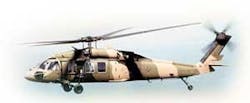
Lightweight materials are essential in designing rotorcraft structures such as those in the UH-60A Black Hawk (Figure 1b). Titanium, magnesium, aluminum, and, increasingly, composite materials are used extensively throughout rotorcraft. Titanium is the primary structural material in Sikorsky rotor designs, while magnesium is used in gearbox housings and aluminum in airframe components. Composites are increasing their usage in blades, rotor head components, and airframe structures.
Rotor components and gearboxes are made from large forged metallic billets. The airframe also contains parts made from forged materials, but the majority of the airframe details are constructed from aluminum sheet metal. The 7000 series zinc-based aluminums are traditionally used due to their good combination of static strength and fatigue properties. While the 7000 series aluminums are excellent for aerospace applications, they are not very tolerant to high heat. Rapid heating, as with welding and laser cutting, can produce micro-cracking, which can reduce fatigue capability. Welding and laser cutting are two processes that can produce the heat-induced micro-cracking.
The ability of laser cutting to quickly and accurately produce shapes out of an aluminum sheet attracted many aerospace companies as soon as laser cutting equipment became commercially available. Major manufacturers reviewed laser cutting in the 1970s and found that laser produced micro-cracking was an unacceptable detriment to fatigue properties. Potential weight increases stifled manufacturing benefits, shelving laser cutting by all major airframe manufacturers.
In addition to micro-cracking issues, it was found that laser cutting manufacturing variables were difficult to control and virtually impossible to inspect. In the current global manufacturing market, tighter control of all processes and verification of properties have become increasingly important as work is increasingly contracted to outside suppliers.
Quality and process control are vital, and any process that contributes to uncertainty in manufacturing should be either brought into control or eliminated. Laser cutting has in the past presented a challenge in control and consistency between batches.
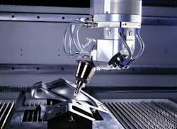
Primary drivers for the restrictions on aerospace laser cutting, reductions in fatigue performance, and manufacturing consistency have been readdressed in current laser cutting systems. Current laser systems have greatly reduced the size of the heat affected zone (HAZ) and the associated micro-cracking. Parameters controlling laser cutting can now be developed and precisely repeated using computer software. These improvements in technology have merited a rethinking of laser cutting for airframe structures made from 7000 series aluminums. A laser cutting machine is shown in Figure 2.
Laser cutting
Fatigue cracking occurs most often at stress concentrations that can be at the edge of the part, at a geometry change, or at a fastener. Sheet metal airframes are assembled using a variety of fastener types with a majority of sheet metal fatigue cracks originating at the fastener locations. Laser cutting effects, if lasers are precluded from fastener holes, are at the cut edge of the part. For independent effects, a weakest link in the chain analogy can be used to show that laser cut edge cracking is less of a detriment than the fastener locations, thus leading to the conclusion that a part that would crack at the fastener would not have its fatigue performance further reduced by the laser.
Riveted structure
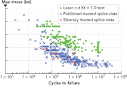
Testing was conducted by Sikorsky Aircraft to investigate the laser edge to fastener-hole fatigue relationship. Laser edge testing used 7075-T6 clad sheet metal cut with typical job shop laser cutting practices. The specimens were tested at various stress levels with a constant R-ratio of +0.1. The +0.1 ratio was selected due to its relevance in fatigue critical airframe structures.
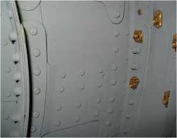
Fatigue performance of riveted structures (Figure 3) was determined using Sikorsky test data and published data from many sources. As is shown in Figure 4, the laser cut edge outlasted the rivet location over the entire spectrum. Testing was conducted from endurance levels to plastic yielding and the laser edge was consistently shown to be less critical. While this is only a first step, it is an important finding demonstrating that lasers could have use in cutting airframe sheet metal.
Comparison of riveted and laser cut testing
Laser cutting produces consistent parts quicker and more cost effectively than conventional machining. Lasers have the potential to reduce both manufacturing time and cost. Historically, advantages of lasers have long been outweighed by the reduction in fatigue lives in 7000 series aluminums. Recent advances in laser systems have given reason to re-evaluate laser cutting of aerospace aluminums. Preliminary testing has shown potential for lasers in airframe manufacturing. Future systems and existing designs should not eliminate the use of lasers based on past experience. We need to stay open minded and evaluate every situation to see if lasers can provide a product benefit.
Technologies that reduce the HAZ and allow a well defined and controlled manufacturing process could produce laser trimmed sheet metal parts that experience little or no fatigue degradation. Laser cutting continues to advance like the technologies that made “heavier than air” vertical flight possible almost 70 years ago. After initially being shelved for aerospace use, aluminum cutting lasers may now have a potential role in producing cost effective, structurally efficient parts.
Dr. Michael Urban ([email protected]) is chief of structural methods and prognostics with Sikorsky Aircraft, Stratford, CT.