Laser drilling aids cool running for gas turbines
Robb Hudson and Richard Baxter
Laser ablation can remove TBC and bond coat before drilling
Both aero engine and industrial gas turbine manufacturers have battled a process chain for many decades in the efficient production of cooling holes in various turbine components. Typically, producers of these parts must drill the cooling holes in these components prior to the application of thermal barrier coatings (TBCs), which are highly advanced material systems applied to the metallic surfaces of gas turbine or aero-engine parts operating at elevated temperatures. These coatings serve to insulate components from large and prolonged heat loads by utilizing thermally insulating materials which can sustain a predictable temperature difference between the base metal alloys and the coating surface. By so doing, these coatings allow for higher operating temperatures while limiting the thermal exposure of structural components, extending part life by reducing oxidation and thermal fatigue. In conjunction with the advancement of active film cooling hole design, TBCs permit working temperatures higher than the melting point of the metal airfoil in some turbine applications.
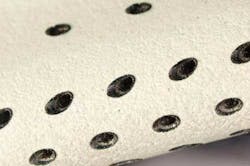
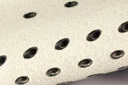
FIGURE 1. TBC removed by laser ablation.
TBC composition
Generally, TBCs consist of four layers: the metal substrate, a metallic bond coat, a thermally grown oxide, and a ceramic topcoat. The ceramic topcoat is typically composed of an yttrium-stabilized zirconium (YSZ), which is desirable for having very low conductivity while remaining stable at nominal operating temperatures typically seen in these applications.
In the past, it is the low conductivity of the ceramic top coat in TBCs that have presented challenges to manufacturers of certain turbine components, i.e., turbine blades and turbine vane segments. The classical process sequence of drilling the various turbine components prior to the coating process has often created a time consuming and costly manual process of clearing the ceramic top coat from previously drilled holes.
Coating before drilling
Manufacturers can now coat these critical life-limited components prior to the drilling process thanks largely to the advancement of laser technology. By employing laser ablation techniques, these turbine companies are now able to gently create a "patch" by clearing the ceramic coating from the surface of the part, exposing the parent material and allowing for conventional drilling methods by way of high powered laser sources or electrical discharge machining (EDM) (FIGURES 1 and 2).
The laser ablation process is usually carried out via a Q-switched Nd:YAG laser or a pulsed diode pumped solid state laser. These ablation lasers are usually 100 W of maximum average power with either laser source. However, the methods of operating the two lasers vary a bit as the diode pumped solid state laser usually has a fixed pulse width and one must manage parameters via diode current. Whereas with a Q-switched Nd:YAG laser, the pulse width is widely variable in the nanosecond range and allows the achievement of a much higher peak energy and power. Regardless of the laser source, the beam delivery is carried out via a 2-axis or 3-axis scanning head also known as a galvanometer. The 3-axis version is used where ablation depths require a focus shift of the laser in order to properly maintain control on material removal and surface quality.
Shaped hole openings
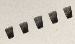
The ablation cycle can be used as well to create very complex shaped diffusion hole openings, allowing for more advanced forms of film cooling to be used on the airfoils in commercial and military jet engines as well as industrial gas turbines. This advanced film cooling design allows for higher firing temperatures of the engines, thereby making them more efficient while simultaneously reducing their emissions into the environment. Processing these unique shapes presents ever-changing challenges to the laser ablation process as diffusion-shaped holes have grown in complexity in recent years. Processing time and volumetric material removal rates are highly variable depending on the shape of the diffuser. These variables relate to verticality of the diffuser walls to overall depth of the shape. Because of the complexity of the shapes, it is imperative to have 3D solid models of these shapes where the models can be imported into a CAM or post processor to more quickly calculate the most concise tool path. Material removal rates slow as the diffusion shape gets deeper and, as material evacuation slows, the cavity grows in size, particularly depth.
Laser ablation provides the perfect solution to machining operations on today's high pressure turbine blades and vanes. The complex and intricate pattern of cooling holes required on these parts are fundamental in satisfying the demands for reduced noise emissions and increased fuel efficiency on the latest generation of engines, such as those used to power the Boeing 787 Dreamliner and the Airbus A350. As the turbine blades and vanes on these engines run at high temperatures that often exceed the melting point of their base metal alloys, they not only require round and shaped cooling holes, but the surface is protected by the TBC.
TBC challenges
The TBC is non-conductive and not conducive to the widely accepted EDM process. It is extremely costly for the manufacturers of all TBC coated turbine components to drill prior to the application of the TBC. The process in which the coating is applied, while controlled better than in the past, still has a tendency to clog the holes as in industrial gas turbine components or to cover over portions of the hole openings as on aero-engine parts. In either case, the air flow for each part is greatly compromised due to the coating. It is an expensive and laborious process to clear the TBC from the holes. Typically the clearing has to be done by hand utilizing high RPM air tools and diamond tipped burrs. This operation is time consuming; the perishable tooling cost of the diamond burrs is high; and the chance of damaging an otherwise finished part is great.
The preference would be to drill cooling holes after the TBC coating has been applied to the part. In some instances, it is possible to use high peak power pulsed lasers to generate the cooling hole. This option can have an impact on hole quality in terms of heat affected zone (HAZ), recast layer, micro-cracking and de-lamination in the interface between the bond coat and TBC. Any one of these scenarios could result in the failure to meet the stringent criteria laid down for components of this type.
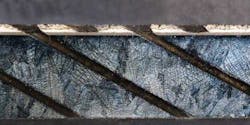
The laser ablation process allows the manufacturer to remove the TBC and bond coat, exposing the parent material. For the case of diffusion shaped holes, the ablation process can also be used simultaneously to create the complex diffuser. Afterward, the manufacturer can drill the metering section of the hole using the conventional methods via EDM or the high peak power pulsed laser (FIGURES 3 and 4).
Combination systems
Combination machining systems are now available in the marketplace from companies such as Winbro that offer laser ablation and EDM drilling or laser ablation and high peak power pulsed laser drilling in the same platform. Now manufacturers are able to take a coated part to a machine and completely drill the component (including diffusion shapes) in a single operation and single workholding while meeting and/or exceeding the stringent quality standards that have been established for these hot section engine components.
For those engine components that have been in production and already have a documented and certified manufacturing process, whereby all drilling must be done prior to the TBC process, laser ablation is still a viable option in replacing the costly, laborious process of clearing the TBC from the previous drilled holes. Salvaging components in this manner has proven to be effective for both IGT and aero engine components and can be performed with high reliability and repeatability.
Each laser source for ablation has unique benefits and drawbacks. Different types of laser sources are appearing as candidates to carry out the ablation process in turbine components as well. It is suggested that if considering this process, one should test both laser sources to determine which is the best fit for the overall application requirements.
Robb Hudson([email protected]) is VP, Winbro Group Technologies, LLC, Rock Hill, S.C. (www.winbrogroup.com) and Richard Baxter is account & marketing manager, Winbro Group Technologies Ltd., Coalville, Leicestershire, U.K.
Past ILS Issues
