Laser processing inside polymers
The processing of 3D parts made of transparent material is possible via nonlinear effects that occur at high laser radiation intensities. A direct laser writing technique for polymerization of photosensitive materials based on a two-photon process was introduced in 2007.6 As an alternative procedure, 3D parts can be separated from a block of transparent plastic material by a novel laser cutting technique developed at the Laserinstitut of the University of Applied Sciences in Mittweida, Germany www.hs-mittweida.de. By using high-intensity laser radiation, locally confined material destruction can occur inside bulk polymers as a result of nonlinear absorption processes. If these microdefects are well-arranged into a cut surface, the 3D part can be separated from the bulk volume.7, 8
Three studied materials
This study investigated three transparent plastic materials: polymethylmethacrylate (PMMA), also known as acrylic glass, is a thermoplastic synthetic material with a refractive index of 1.49 at a wavelength of 1 micron. Polycarbonate (PC) is a polymer ester of carbon acid and diol and has a refractive index of 1.57. Cyclo-olefin-copolymers (COC) consist of olefins and have an amorphous structure with a refractive index around 1.53. In the investigations, a high repetition rate ultrashort laser system from Clark MXR Inc. http://www.cmxr.com was used, delivering 180 fs short pulses at a wavelength of 1030 nm.
In technical grade PMMA, single defects can be generated at a pulse energy level of several micro joules. As can be seen in FIGURE1a, the defects with a distance of 15 µm to each other show a void-like appearance with a lateral diameter of 5 µm. Along the direction of the incident laser beam (axial direction), filament formation was observed in addition to the generated defects. Filament formation has been discussed for irradiation inside bulk glass with high-intensity laser pulses.1, 9 As a result of filament formation, it is difficult to estimate the axial extension of a single defect. With optimal parameters, the size ranges approximately between 50 µm and 100 µm with a sharp boundary directed toward the incident laser beam and a blurred appearance, which migrates into filament-like structures in deeper regions, as shown in FIGURE 1b.
For defect generation in PC and COC, the investigations reveal identical process parameters in comparison to PMMA processing. But, in contrast to PMMA, the materials PC and COC show blackening after laser irradiation, which originates from released carbon inside bulk polymer due to laser induced bond breaking of C-C bonds and C-O bonds at high intensities of laser radiation. The effect depends on the carbon-to-oxygen ratio because a high amount of oxygen allows an oxidation to carbon dioxide, and a low concentration of oxygen means carbon remains, which is responsible for blackening. So the carbon-to-oxygen ratio is more disadvantageous for PC than for PMMA, and, in the case of COC, oxygen is entirely missing, and blackening remains. In conclusion, polymers with a low content of oxygen in comparison to carbon are less suitable for the presented 3D cutting technology.
To produce 3D parts, an appropriate irradiating strategy was developed. An irradiation regime was found that arranges the single defects into a cut surface, which encloses the part to be excised. The optimum laser pulse distances for cut surface formation are approximately equivalent to the achieved lateral and axial defect dimensions of a single defect. 3D parts were processed in a layer by layer strategy, starting at the bottom and advancing upward. To release the 3D part easily from the bulk volume, additional well-arranged cut outs are inserted.Software for more complex parts
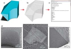
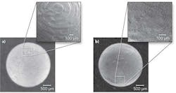
For the fabrication of more complex shaped 3D parts, the laser beam path cannot be programmed manually without unreasonable effort. Hence, special software was used to generate a motion program for the laser beam path automatically deduced from the geometry data of the part. Today, there are CAD-CAM solutions available, e.g. DCAM from SKM Informatik GmbH (http://www.skm-informatik.com), which support the entire processing of 3D parts beginning with the construction of the geometry until the generation of the laser beam path, as shown in FIGURE 2a-c. By using customized post-processing software, the calculated laser beam path can be processed directly by the respective laser system. Using this CAD-CAM solution, a demonstrator structure was fabricated from bulk PMMA, as shown in FIGURE 2b. The walls were very smooth and free of cracks, and the dimensions showed a deviation of less than 50 µm in comparison to the given dimensions, consequently a very precise fabrication process can be achieved. Furthermore, the demonstrator structure impressively demonstrated the possibility to generate 3D parts containing undercuts in their geometry. In order to evaluate the surface quality of the 3D parts, roughness measurements were conducted with a confocal point sensor µScan from NanoFocus AG (www.nanofocus.de). For PMMA, the measurements reveal a maximum roughness of 4.5 µm and an averaged squared surface roughness (EN ISO 25178 standard) of 1.5 µm.However, this approach reveals disadvantages regarding more complex curved parts containing spherical surfaces; for instance, commercially available CAD-CAM programs enable the slicing of the 3D geometry with equidistant layer distances. For that, FIGURE 3a shows a sphere with equidistant layer distances. A poorer resolution can be observed at the polar caps of the sphere due to a constant layer distance and therefore cumulatively larger steps in lateral direction, which is demonstrated in FIGURE 3a. Consequently, for 3D parts with curved surfaces, there exist higher requirements regarding laser processing: the pulse distance in axial direction and thus the distance of the layers are a function of the inclination of the surface with cumulatively lesser layer distances at the polar caps in comparison to the equator. By using a self-developed software tool, which calculates the motion program based on specified equidistant pulse distances along the surface of a sphere, a homogenous resolution has been achieved throughout the entire surface of the sphere, as shown in FIGURE 3b.
Deduced from those experiments for 3D parts with complex and irregular curved surfaces, in the next step special algorithms will be implemented into CAD-CAM tools, which consider the inclination of the surface.
Conclusion
With the presented rapid tooling technology, 3D parts consisting of transparent polymer material can be produced with an overall dimension of a few millimeters. Depending on the complexity of the geometrical shape, the processing time lasts a few minutes. This is a big advantage in comparison to laser induced polymerization techniques, which consume hours or even days. By applying additional processing steps, such as polishing or laser microstructuring, the functionality of the part can be increased. Consequently, the presented technology is suitable for applications in microsystems technology or biomedicine for instance.
REFERENCES
1. D.G. Papazoglou, I. Zergioti, S. Tzortzakis, G. Sgouros, G. Maravelias, S. Christopoulos, C. Fotakis, “Sub-picosecond ultraviolet laser filamentation-induced bulk modifications in fused silica,” Appl. Phys. A 81, 2005, pp. 241–244.
2. K.M. Davies, K. Miura, N. Sugimoto, K. Hirao, “Writing waveguides in glass with a femtosecond laser,” Opt. Lett. 21, 1996, p. 1729.
3. E.N. Glezer, M. Milosavljevic, L. Huang, R.J. Finlay, T.-H. Her, J.P. Callan, E. Mazur, “Three-dimensional optical storage inside transparent materials,” Opt. Lett. 24, 1996, p. 2023.
4. E. Bricchi, J.D. Mills, P. Kazansky, B. Klappauf, J. Baumberg, “Birefringent Fresnel zone plates in silica fabricated by femtosecond laser machining,” Opt. Lett. 27, 2002, pp. 2200-2202.
5. S. Nolte, M. Will, J. Bughoff, A. Tuennermann, “Femtosecond wave-guide writing: A new avenue to three-dimensional integrated optics,” Appl. Phys. A 77, 2003, pp. 109-112.
6. C. Reinhardt, A. Ovsianikov, S. Passinger, B.N. Chichkov, “Fabrication of micromechanical and microoptical systems by two-photon polymerization,” Conference Photonics West 2007, Proceedings of SPIE, Vol. 6466, MOEMS and Miniaturized Systems VI, January 2007, San Jose, CA, USA, pp. 1-9.
7. U. Loeschner, S. Mauersberger, R. Ebert, H. Exner, J. Schille, P. Regenfuss, L. Hartwig, “Micromachining of glass with short ns-pulses and highly repetitive fs-laser pulses,” Proceedings of the ICALEO 2008, 27th International Congress on Applications of Lasers and Electro-Optics, Temecula, USA, pp. 193-201.
8. U. Loeschner, S. Mauersberger, J. Schille, R. Ebert, H. Exner, “Machining of transparent materials with short pulse and ultrashort pulse laser sources,” Proceedings of the 5th Int. WLT-Conference on Lasers in Manufacturing, June 2009, Munich, Germany, pp. 659-665.
9. V.P. Kandidov, O.G. Kosareva, I.S. Golubtsov, W. Liu, A. Becker, N. Aközbek, C.M. Bowden, S. L. Chin, “Self-transformation of a powerful femtosecond laser pulse into a white-light laser pulse in bulk optical media or supercontinuum generation,” Appl. Phys. B 77, 2003, pp. 149-165.
About the Author
Udo Loeschner
Professor of Laser Manufacturing Technology, Laser Institute of Mittweida
Udo Loeschner is Professor of Laser Manufacturing Technology at the Laser Institute of Mittweida (Mittweida, Germany).
Jörg Schille
Laser Institute of Mittweida
Jörg Schille is with the Laser Institute of Mittweida (Mittweida, Germany).
Horst Exner
Laser Institute of Mittweida
Horst Exner is with the Laser Institute of Mittweida (Mittweida, Germany).
Robby Ebert
Laser Institute of Mittweida
Robby Ebert is with the Laser Institute of Mittweida (Mittweida, Germany).


