Remote laser welding in automotive production
Martin Bea, Ruediger Brockmann, & David Havrilla
Greater flexibility in part manufacturing is a key asset
More Industrial Laser Solutions Articles |
Laser-GMA hybrid joining of thick high-strength steels |
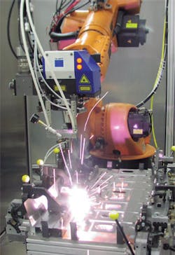
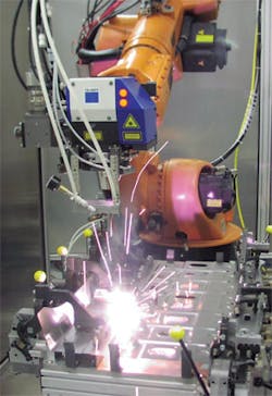
Every minute the laser is waiting for parts, the welding system is literally in a holding pattern, which decreases the potential for increased throughput and revenue. To counteract this and maximize the economic justification for a laser welding system, the "beam on part" time should be as close as possible to 100%. One thing that can be done to maximize "beam on" time is to utilize a process that has become known as remote welding.
The scanning optic or PFO (programmable focusing optic) at the end of the laser's fiber optic cable is the central element for precise positioning of the laser's focus point on the component to be welded. Inside the PFO, two scanner mirrors direct the beam through a "flat field" optic, which focuses the beam onto a common focus plane no matter where it is in the work envelope of the PFO. The PFO is also equipped with a motorized lens that allows the focus plane to be moved up and down in the Z axis. The repositioning of the focused laser beam from one end of the entire work envelope to the other takes a mere 30 milliseconds.
Remote welding on the fly
There are three basic preconditions for welding on the fly: First, a solid state laser is needed as the beam source. Solid state lasers enable delivery of the laser beam through a highly flexible fiber optic cable, which is required when joining components in 3D space with a multi-axis robot.
Second, a laser with excellent beam quality and the appropriate power is required. Beam quality is the measure of focusability of a laser, and the long focal lengths required for remote welding necessitate superior beam quality (i.e. 4 to 8 mm-mrad) in order to achieve the appropriate focused spot size (i.e., about 0.6 mm) at the workpiece. For remote welding in automotive body production, typically about 4 to 6 kilowatts of laser power is used.
The third essential precondition is precise positioning of the weld seams, which requires axis synchronization between the robot and the scanner control. This allows the weld shape programmed in the scanner control, let's say a "C" shape, to really be a "C" shape with the robot moving at various speeds over the part to be welded. Some control architectures use "time" synchronization. The problem here is that if the robot speed is changed for any reason, the weld shape will also change because the axes are not synchronized.
Optimizing the process
Welding patterns in any selected shape and size can be achieved when welding on the fly with a PFO. Independent of robot speed, precise weld shapes can be used in the joining of components - a task that a rather clumsy and imprecise robot cannot attain.
Though linear welds require significantly less flange width than a resistance spot weld, sometimes other shapes, such as a C or staple-shaped weld, provide the ideal balance between increased strength and reduced weight (FIGURE 2). Whether short lines, circles, C-shaped or S-shaped welds, the size, arrangement, and orientation of the laser weld seams allow for optimized weight and strength of the welded assembly.
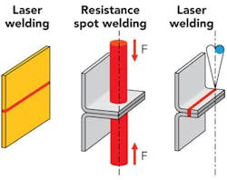
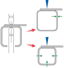
Besides being able to optimize both strength and weight through strategic employment of weld seam shapes, laser welding's single-sided access provides another advantage compared to resistance spot welding's double-sided access. Closed cross sections, such as tubes and profiles used for frames, are much more rigid compared to open sections and formed sheet metal, thereby increasing vehicle strength while reducing weight and cost.
Maximizing throughput
Compared to resistance spot welding, on the fly laser scanner welding represents a significantly more efficient alternative for an increasing number of automotive components. The relatively long re-positioning times associated with moving the spot welding gun from one weld location to another are almost completely eliminated with remote scanner welding. The continuous motion of the scanner head in combination with the rapid positioning of the laser focus point by the scanner mirrors accounts for the dramatic increase in throughput. Not only this, but producing a laser weld with the identical strength of a resistance spot weld requires only a fraction of the time.
These time savings increase the throughput of welded assemblies and the number of seams produced on them. For the body in white shop, where sheet metal thicknesses are typically in the range of 0.6 to 1.8 mm thick, each weld spot requires about two seconds, whereas a comparable laser weld seam can be generated in less than 0.4 seconds. Thus, the welding time alone is reduced by a factor of five.
Paradigm for series production
Daimler AG was the first automobile manufacturer to use on the fly remote welding in series production. For this purpose, Daimler developed the "RobScan" process, which it has been using since 2007 at its factory in Germany (Bremen & Sindelfingen) and South Africa (East London) to weld C-class automotive body components. Today, nearly 70 RobScan systems are in use. The RobScan systems are equipped with the PFO 33 scanner and over 30 diode pumped disk lasers with output powers ranging from 3 and 4 kilowatts.
Since January 2009, Daimler has been working with the second generation of RobScan. Further optimized production quality and cost efficiency, due to shortened cycle times and improved utilization of the installed laser power, are among the advantages. These are achieved by means of four innovations: 1) Variable focus position of the laser beam along the Z axis, 2) reduced weld penetration, 3) further development of on-line weld quality control, and 4) off-line simulation in system programming.
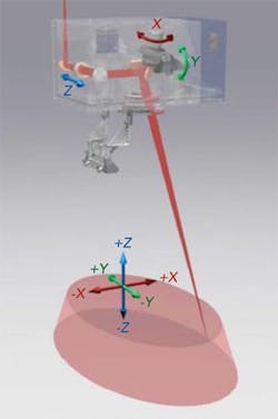
The additional Z axis in the PFO 3D makes it possible to weld at different distances from the scanner optics, or up or down an incline, without changing the robot path in the Z axis (FIGURE 3). Reducing penetration from full to partial decreases the amount of weld spatter and increases process speed without impacting weld strength.
The robot path can be programmed offline with new CAD simulation tools. The system tests the accessibility of all weld seams, carries out a collision test with the clamping device and optimizes the coordination of robot and scanner movement. This reduces installation and change-over time, improves the cycle times, and helps in the equipment planning of complex installations. Off-line simulation also ensures that the robot path and travel speed have been optimized.
Twenty systems of the new RobScan generation with the PFO 3D scanner have been added for E Class production at Sindelfingen. In the C and E class car bodies, welding on the fly with the new RobScan process has replaced up to 15 percent of the resistance weld spots. Seven 6 kilowatt disk lasers are used at Sindelfingen for production of the E class. By using the new scanner optics and the advanced robot path and simulation tools, the company was able to make further reductions in the number of remote systems needed for the E class series production.
Efficiency increase
One on the fly laser welding station replaces up to five conventional resistance spot welding stations. At the same time, just one or two clamping stations are enough to join structural components. This allows users to open free spaces in production because different components can be processed, or different processes, such as laser dimpling in addition to the laser welding, can be carried out all in one single laser welding station. In comparison to resistance spot welding, production time has been reduced by up to 80 percent.
If just the processing speeds are compared, the welding speed at a laser power of 4 kilowatts is about six times faster; at 6 kilowatts, it's about ten times faster. At high duty cycle and maximum laser output power, a five-fold higher production capacity is possible.
The advantages are not only quantitative; there are also advantages in quality of parts because remote laser welding decreases production tolerances. On the one hand, it subjects the parts to less heat input and mechanical stress than the usual welding processes. The parts are not distorted as much and their structural geometry is not affected. On the other hand, the lower number of positioning and clamping procedures contributes to an even greater dimensional stability of the welded components as well as the entire car body.
As a result of the advantages in component and vehicle properties, the overall costs of remote laser welding compared to resistance spot welding are favorable in spite of the relatively high cost of the production tool and laser. The savings achieved are associated with significantly greater flexibility because it is possible to weld different car body styles on the same remote welding line. For a long time already, the use of remote processing has not been restricted to doors, sidewalls, or rear center assemblies made of sheet metal. More and more automotive part suppliers use it to produce other subassemblies such as bumpers, rocker rails, wheel wells or instrument panel carriers.
Design for laser welding
Laser welding will continue to take its place in the fabrication of car bodies. How quickly that will happen depends primarily on the designers' increasing awareness of the advantages of this laser process. The greatest advantages in costs and productivity compared to resistance spot welding can be achieved when components are intentionally designed or re-designed to take advantage of the laser joining process. Here are a few considerations:
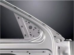
- Reduce the component weight and cost by reducing or even eliminating flange widths (enabled by single sided, narrow beam access) - FIGURE 4
- Reduce the component weight and cost by reducing gage thickness (enabled by using optimized weld shapes or continuous weld seams in high stress regions of parts normally spot-welded together)
- Reduce the component weight and cost and increase strength by elimination of access holes in structural reinforcements needed for resistance spot back-up electrodes - FIGURE 5
- Reduce the as-welded distortion and thereby reduce or eliminate post process rework or straightening due to the low heat input associated with the laser welding process, or by reducing the number of processing steps and associated fixtures
- Eliminate secondary processes such as grinding and finishing by taking advantage of the high weld seam aesthetics
- Employ unique styling of components enabled by laser welding and/or laser brazing (e.g., laser brazing of an automotive ditch joint thereby eliminating sealing and the use of plastic molding to "fill-in" the ditch).
Those who thoroughly consider these points are on the right track to benefiting the most from laser welding. ✺
Dr. Martin Bea is branch manager automotive and Dr. Ruediger Brockmann is industry manager automotive, both of TRUMPF Laser and Systems Technology, Ditzingen, Germany. David Havrilla is manager, products & applications, TRUMPF Inc., Plymouth, MI, US, [email protected].
