High speed laser drilling of solar cells
Mathew Rekow and Richard Murison
Emitter wrap-through technology is key
Industrial lasers have been widely adopted in the manufacture of thin-film solar cells, mostly for scribing and edge deletion processes, so much so that this market segment is now one of highest value global consumers of industrial lasers. Despite this, and despite a large number of successful technology demonstrations, lasers have yet to make a major impact in the manufacture of c-silicon solar cells, the workhorse of the solar industry. A recent review article indicates that one key reason has been the rapid pace of industry expansion in recent years.1
Manufacturers have preferred to devote their resources to managing a challenging capacity ramp without exposing themselves to the perceived risks involved in introducing new technologies. However, at the industry’s current level of maturity, technology advances — in many cases involving laser-based processes — are becoming more and more attractive as manufacturers seek to differentiate their products in the face of fierce competition. One of these new technologies that promises significant improvement in cell efficiency is known as emitter wrap through (EWT). To enable EWT technology and meet required manufacturing throughput rates, it is necessary to drill an array of 10,000 to 20,000 holes through an 180 µm thick silicon wafer in about 1 second. These holes are typically required to be quite small — about 40 µm in diameter or less — and are distributed evenly across the wafer in a regular grid with about 1 mm spacing.
Emitter wrap through (EWT) solar cells
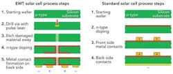
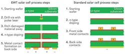
The EWT process has been established as technically viable by various groups.2 In traditional c-Si solar cell technology, the front surface of a p-type Si solar cell is doped with phosphorus to become the “emitter,” the surface where the positively-charged photo-generated carriers are collected. A metallic grid is then printed on this surface that leads to bus bars for collecting the generated photo current. Among other deficiencies, this architecture has the drawback that a portion of the active surface of the solar cell is shaded by the bus bars and collection grid. Consequently, techniques to eliminate these electrical traces without significantly increasing manufacturing complexity continue to garner interest. EWT regains this lost surface area by “wrapping” the emitter through the wafer to the back side so that gridlines and bus bars can be applied to the back side of the wafer rather than taking up valuable electricity producing area on the front side. The large number of holes drilled through the wafer also result in some lost electrical generation area; however, this is orders of magnitude less than what is lost due to shading by the grid lines and bus bars. The EWT structure is compared to an idealized standard c-Si solar cell structure in FIGURE 1. This figure shows an additional benefit: with EWT, the average distance a photo-generated minority carrier has to travel from within the bulk of the cell to reach the “emitter” is almost halved, which results in gains due to improved carrier collection.
Questions remain, however, regarding the ability to reach the required processing throughput of about 1 wafer per second at a reasonable capital cost. Data obtained to date indicates drilling rates of 4,000 to 5,000 holes per second (hps) can be achieved using specialized drilling lasers of approximately 100 W average power3, 4 which, taken at face value, seems to indicate that achieving the required 10,000 to 20,000 hps would incur a very high capital cost for laser sources and their integration. In our work we studied the impact of laser pulse parameters on the potential drilling rates for the EWT process. We also considered the physics at work for material removal under the various pulse parameter regimes, and reported high speed drilling of EWT via holes at potential rates of more than 10,000 hps using only 22 W of laser power.
Experimental setup and materials
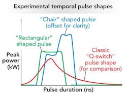
The tailored-pulse laser. The PyroFlex-25, a 25 W, 1064 nm pulse programmable fiber laser, was utilized for these experiments.5 This fiber laser technology allows us to vary pulse durations from 2 ns up to 700 ns, independent of laser repetition rates, which are variable from 10 to 500 kHz. In addition to the extremely wide range of available pulse duration, the temporal pulse shape can be arbitrarily programmed to generate a specific desired temporal profile of instantaneous laser power. In these experiments laser pulses were mostly limited to “rectangular” shapes to minimize energy lost into non-ablative heating and maximize the efficiency of drilling (FIGURE 2). Ten W of 532 nm light was also utilized, but no significant benefit in the drilling process compared to 25 W of 1064 nm light was observed.
The drilling process. A galvo-scanner with a 100 mm focal length scan lens was utilized for high speed beam positioning, and laser pulses were synchronized with the scan motion. The spot size was approximately 30 µm and approximately 22 W of laser power was delivered to the work surface. There are two distinct ways of drilling large arrays of holes in this set-up. The first is synchronous drilling, where the laser beam is scanned repeatedly over the entire target pattern so that the effective percussion drilling rate on any one hole is approximately the laser repetition rate divided by the total number of holes being drilled. The second is point-to-point drilling where each hole is completely drilled with successive laser pulses at a very high repetition rate, and the beam is then moved on to the next hole location. We utilized both techniques in our study. The silicon wafers used for the experiments comprised standard, untextured, polycrystalline solar cell stock, 180 ± 20 µm thick.
Results
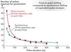
1. Pulse duration dominates material removal efficiency. Common models for laser ablation processes attribute the development of hot plasma as the motive force that ultimately removes material.6 This plasma plume tends to be opaque to laser light and hence for pulse laser machining, the rate that pulses can be delivered to the work piece is limited by this “plasma screening” effect. This is one reason often cited for utilizing synchronous drilling rather than point-to-point drilling, namely to reduce the effective repetition rate on any one hole, thus avoiding “plasma screening”. We find, however, that with our rectangular pulses this effect holds true only for relatively short pulse durations. FIGURE 3 contrasts the result of two drilling experiments, one with synchronous drilling and the other with point-to-point drilling under otherwise identical laser pulse conditions. The data clearly indicate that for pulse durations longer than about 100 ns, there is no apparent “plasma screening” effect and that point-to-point drilling in fact becomes slightly more efficient with regard to the number of pulses required to complete the via hole. This is likely due to significant residual heat left over from pulse to pulse.
Since we see little evidence of significant plasma screening for longer pulse durations, it seems reasonable to consider the hole-drilling mechanism simply from a melt and vaporization perspective. A simple calculation can estimate the total energy required to melt and vaporize the volume of Si that has been removed from the holes. This calculation indicates that 1.5 mJ of energy is required to melt the volume of Si contained in a 40 µm diameter hole, and about 8 mJ of energy is required to completely vaporize it. This contrasts with the results in FIGURE 4 that show via holes of comparable dimensions formed with only about 4 mJ and 2 mJ of total pulse energy, respectively. This observation indicates that only half, or less, of the Si is actually vaporized and, further, that there is little if any excess energy available to ionize the vapor. A significant fraction of the Si must therefore be expelled from the hole in a liquid state, most likely due to the conversion of a fraction of the melt to a rapidly — even explosively — expanding vapor phase. The argument can be extended to shorter pulse durations, where the material removal rate is much reduced, and there is more total energy delivered to the via hole than is required in theory to vaporize the volume of silicon removed. An excess of energy is therefore available to ionize plasma and thus to create plasma screening.
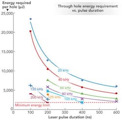
With this model we now infer that the volume of melt produced by a single laser pulse is limited by the rate at which the melt front propagates into the silicon, a conclusion also drawn by other groups7. Although the absorption of 1064 nm radiation in silicon is complicated by very strong temperature dependence, the propagation of the melt front can be seen as a diffusion-like process, which proceeds until the onset of vaporization and melt ejection. This in turn gives a simple basis to understand why a hole drilling process requires less energy at longer pulse durations as indicated in FIGURE 5; reducing the rate of energy delivery allows more material to melt before vaporization drives the molten material away from the surface. Furthermore, the data in FIGURE 5 indicate that the total energy requirement also decreases as repetition rate increases. This reflects the fact that pulse energy decreases with increasing repetition rate due to the average power limitations of the laser. As long as there is enough excess energy to eject the melt, the amount of material removed is primarily a function of the pulse duration rather than pulse energy content, thus, to a point the material removal process becomes more “energy efficient” as pulse energy drops (repetition rate increases).
Finally the data all trend toward a lower limit of pulse energy, both with increasing pulse duration and increasing laser repetition rate, at which via formation ceases. In the most simplistic interpretation, this lower limit reflects the point at which the excess laser energy, beyond what is required to sustain the expanding melt front, is no longer sufficient to generate enough vapor to expel the melt. This can be qualitatively perceived by contrasting the left and right SEMs of FIGURE 4. In FIGURE 4 (left), the laser energy is well in excess of the minimum required to generate enough vapor for efficient expulsion, resulting in a relatively clean hole with vertical side walls. In FIGURE 4 (right), the energy is near the lower limit and the melt is less energetically expelled, resulting in more recast and more taper to the via walls.
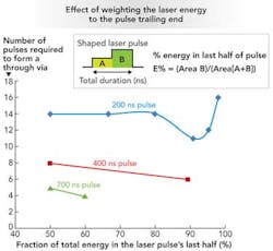
2. Temporal pulse shaping improves drilling efficiency. With this understanding of the material removal dynamics, we can move on to consider the impact of the temporal distribution of laser energy within the pulse. Since thermal conduction rates appear to be the governing factor for the volume of melt, and excess laser energy beyond the melt requirement results in partial vaporization and expulsion of the melt, we hypothesized that weighting the pulse energy content toward the back end of the pulse may have a beneficial effect. In the early part of the pulse, slow energy delivery produces the largest possible melt volume. In the later part of the pulse, the energy delivery is boosted to transition the process from melt formation to vapor formation (and melt ejection). FIGURE 6 shows the result of an initial set of exploratory tests and clearly indicates that increasing the proportion of the pulse energy contained within the last half of the laser pulse has a beneficial impact on drilling efficiency. This compares and contrasts with process dynamics at work with a Q-switched laser pulse, where the temporal pulse shape peaks relatively early in the pulse before giving way to a long, decaying tail (FIGURE 2). The Q-switched laser appears to deliver high energy at a time (early in the pulse) when low energy delivery would appear to be called for, and low energy delivery at a time (later in the pulse) when high energy delivery would appear to be called for. The net result would then be that a larger fraction of the laser pulse energy is consumed in excess vaporization and possible ionization of the ablation plume.
3. Fastest drilling rates are achieved with a “chair” shaped laser pulse. The fastest drilling rates were achieved using a 700 ns “chair” (FIGURE 2) shaped pulse, having 60% of the pulse energy contained in the second half of the pulse. Morphology was qualitatively similar to FIGURE 4 (right). This result was obtained in point-to-point mode, with the laser running at 50 kHz repetition rate, and directing four consecutive 450 µJ pulses to each hole location. This translates to an effective drilling rate of 12,500 via holes per second, with only 1.8 mJ of total pulse energy required to complete the hole. With the set-up we are using, we are limited to processing runs over an area approximately 1 inch square. Within this area, all of the holes were required to achieve break-through for the result to be deemed valid. The most vertical side walls and cleanest morphology were achieved with the 400 ns rectangular pulse, although at a significantly reduced effective drilling rate of 5,000 hps; see FIGURE 4 (left).
Conclusion
We conclude that the use of temporally shaped pulses, when applied to the drilling of via holes in silicon, can enable effective drilling rates that are high enough to support cost-effective EWT manufacture. EWT does not require physically large holes, and we have demonstrated the effective drilling of 25 µm via holes in 180 µm thick silicon, at effective drilling rates of up to 12,500 hps utilizing only about 22 W of average laser power. Temporal shaping and the flexibility of the laser source to span a large range of pulse durations has allowed us to develop some additional insights into the nature of the physical processes which happen during via drilling, and we anticipate further refinements in this area as our work progresses. As development of complete solar cell architectures utilizing the EWT concept nears the point of early deployment, we believe laser technology is now beginning to demonstrate the capabilities necessary to support it. ✺
References
1. Corey Dunsky, “Laser processes in PV manufacturing: An Update,” Industrial Laser Solutions, July/August 2011.
2. J. Gee, “Growing demand for solar power also calls for new material designs,” Laser Focus World, May 2004.
3. Henrikki Pantsar, Private communication.
4. “Laser process optimization for improving emitter wrap through drilling rates,” H. Pantsar, Honolulu: IEEE PVSC Proceedings, 2010.
5. R. Murison, et al. US Patent 7742511 2008.
6. LIA, LIA Handbook of Laser Materials Processing, Orlando: Magnolia Publishing Inc., 2001, 0-94146302-8.
7. Sami T. Hendow, Sami A. Shakir, “Structuring materials with nanosecond laser,” 10, s.l., Optical Society of America, 2010, Vol. 18.
Mathew Rekow([email protected]) is a principal applications engineer and Richard Murison is chief technology officer and director of product marketing, both at PyroPhotonics Lasers, a subsidiary of ESI Inc.
More Industrial Laser Solutions Current Issue Articles
More Industrial Laser Solutions Archives Issue Articles
