Enhancing laser thin-film ablation
STEFAN RUNG, CHRISTIAN BISCHOFF, ERWIN JÄGER, and RALF HELLMANN
Thin-film laser ablation of transparent conductive oxides is commonly performed with Q-switched lasers with nanosecond pulses. With the rising availability of suitable ultrashort-pulse laser systems, manufacturers face the decision of investing in new laser systems to achieve higher process quality and throughput. By applying diffractive optical elements—like beam shapers and beamsplitters—and existing utilities based on nanosecond laser-built manufacturing systems, improvements in thin-film ablation performance towards higher process quality and efficiency can be achieved.
To highlight the advantage of laser beam shaping, indium-doped tin oxide (ITO) is processed with a Nd:YVO4 diode-pumped solid-state laser (DPSSL) using different diffractive top-hat beam shapers and a fourfold beamsplitter. The generated top-hat laser beam profile allows scribing continuous lines with a small pulse to pulse overlap; i.e., with an exceptionally high scribing speed. The beamsplitter is used for parallel processing—that is, increasing throughput and a sustainable usage of the provided laser energy.
Thin-film laser processing
Laser processing has become an indispensable manufacturing technique in thin film technology. Especially in thin-film solar cell processing, the laser-based structuring of individually deposited functional layers is typically performed using DPSSLs with a Gaussian beam profile, different wavelengths, and pulse lengths in the nanosecond regime. The respective laser scribing processes are generally referred to as P1 (structuring the transparent conductive oxide layer), P2 (patterning the semiconductor absorbing layer), and P3 (patterning the contact layer).
In particular, the P1 scribe of transparent conductive oxides (TCOs) can also be found in the production of display devices, touchscreens, and organic light-emitting diodes (OLEDs). Laser scribing, as opposed to traditional methods such as mechanical needle scratching or wet chemical etching, is associated with a minimum of mechanical stress to the thin layer and circumvents an objectionable chemical treatment. Although ultrashort-pulsed laser systems have been proven in scientific studies to yield superior process quality and high throughput, the state-of-the-art industrial laser ablation systems for thin-film scribing are still Q-switched DPSSLs with nanosecond pulses. To further advance their performance, beam-shaping optics can be easily implemented into existing manufacturing systems to optimize the beam profile and multiply the output beam for parallel processing purposes.
Top-hat profile for enhanced film ablation
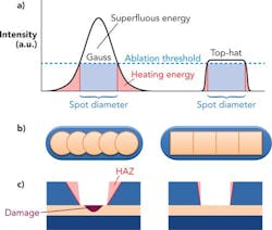
The main drawback with using lasers having a Gaussian beam profile is to manage the energy deposited into the material. FIGURE 1 illustrates the principle of the ablation behavior of thin films. Complete ablation is achieved only in an area where the laser intensity exceeds the ablation threshold. Any energy above this threshold may damage the underlying substrate material. The energy in the wings of the Gaussian profile is below the ablation threshold and leads to an undesired heating of the surrounding material, which in turn can lead to a structural damage. According to Keming Du, up to 36.8 percent of the energy within a Gaussian beam is effectively used for the ablation of thin layers.1 As shown in FIGURE 1a, a top-hat beam profile can significantly improve this energy match to the ablation threshold, by means of which both the excess energy above the threshold and the excess energy in the wings can be reduced. As a result, potential damage to the substrate beneath the laser scribe and the adjacent area can be avoided.
A further advantage of using a beam shaper to generate a top-hat profile is the possibility to change the laser footprint from a circular type to a square or a rectangular one. Typically, structuring with a pulsed laser having a circular footprint leads to a sawtooth-type pattern along the ablated line, which can induce unwanted mechanical stress in the thin film. To avoid this, it is necessary to use a high pulse overlap of at least 70 percent when working with a circular Gaussian beam profile.2 In contrast, a rectangular footprint can produce straight walls with a very small overlap, thus increasing the processing speed of the laser micromachining.3-5
Different top-hat beam profiles for diverse tasks
In the following section, valuable rules of practice are summarized for using refractive and diffractive beam-shaping optics for top-hat profiles. The spot size of an unshaped beam profile in the focal plane is determined by the wavelength, the numerical aperture (NA) of the focusing optics, and the input beam quality. A redistribution of this intensity profile into a homogeneous top-hat beam profile can fundamentally only be realized by a widening of this spot size. The magnitude of this spatial expansion depends on the particular physical approach of beam shaping, with the homogenization of the beam profile being possible in one or two dimensions.
DPSSLs used for thin-film processing typically exhibit diffraction-limited, single-mode Gaussian beam profiles (TEM00) in the focal plane. As a rule of thumb, with refractive beam shapers, the minimum top-hat size (at 1/e2-limit) is at least 4X bigger than an unshaped, diffraction-limited TEM00 spot. Besides this limitation of minimum feature size, refractive beam shapers allow generating top-hat profiles in the range of up to a centimeter and can work also with multimode lasers (FIGURE 2). However, in thin-film laser ablation, a large spot size will remove more material and thereby decrease the active area of the device.
Alternatively, top-hat sizes close to the diffraction limit can be generated by using diffractive beam-shaping elements. Each focus beam shaper (FBS) allows the generation of two different top-hat profiles in the working plane. The so-called zero-order top hat is just 1.5X bigger than an unshaped, diffraction-limited TEM00 spot, whereas the first-order top hat is 3X bigger than the unshaped, diffraction-limited TEM00 spot. The following two formulas give an estimate of the top-hat focal size in the zero and first orders of FBS elements. In addition, FBS elements provide very high efficiency (>95 percent) and lead to a high homogeneity (±2.5 percent) within the generated top-hat profile. Typical tolerances for variation of input beam size and lateral misalignment are approximately 10 percent of the used beam diameter. The input beam quality should be better than M2 = 1.5.
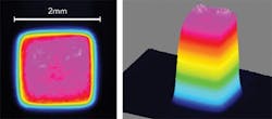
FIGURE 3 illustrates the footprint geometry of the zero-order top hat of two different top-hat FBSs, denoted as FBS-1 and FBS-2. These two diffractive optical elements differ in their spatial modulation, which in turn leads to different intensity distributions of the diffracted optical field. In particular, FBS-1 generates a top-hat beam profile in the focus with a square-type footprint, yet with rounded corners. The conversion efficiency of FBS-1 is about 95 percent. In contrast, FBS-2 generates a top-hat beam profile with the sharp edges of the square-type footprint. However, the conversion efficiency of FBS-2 is slightly reduced to about 90 percent.
The zero-order top hat of FBS-2 also shows a very high depth of working area around the focal plane (depth of focus). Both the intensity distribution and the size (@1/e2-level) of the profile are rather stable within this area, which leads to an almost constant power density. The length of the zero-order top-hat working area is approximately 60 percent of the Rayleigh length of a Gaussian-type beam profile. Within this zero-order top-hat working area, the peak intensity of the top-hat beam drops by only about 15 percent, as compared to a Gaussian beam that would drop by about 30 percent over this length scale (over the entire Rayleigh length, the peak intensity of the Gaussian beam drops by 50 percent). This reduced variation of the FBS-2 zero-order top-hat peak intensity permits more stable thin-film ablation processes.
The different laser beam profiles of FBSs can be used to remove thin films with very high scribing speed. FIGURE 4 compares the thin-film ablation of a 150nm ITO with a 1064nm Nd:YVO4 DPSSL at a repetition rate of 10kHz. For applications that require a diffraction-limited spot size, the zero-order top hat of FBS-1 or FBS-2 can be used. FIGURE 4a shows a laser-scribed line using a zero-order top hat of FBS-1. As outlined above, the application of a top-hat beam profile facilitates a significant reduction of the spot overlap down to about 10 percent. However, the slightly rounded corners of the beam profile using FBS-1 are still noticeable.
A laser-scribed line using the zero-order top hat of FBS-2 with the same ablation spot overlap is shown in FIGURE 4b. The improved intensity distribution enables laser scribing of straight lines without sawtooth-shaped edges.
Finally, slightly changing the optical setup allows the generation of a first-order top-hat beam profile with the FBS-1. By employing this higher order, it is possible to work with a homogenous laser beam profile with sharp edges in the case of FBS-1, yet with a larger spot diameter. FIGURE 4c depicts a laser-scribed line with a laser spot overlap of 10 percent, similar to FIGURE 4a. Contrary to the results shown in FIGURE 4a, FBS-1 also allows the removal of straight lines when using the first-order top hat.
These results highlight that the application of a homogenous laser beam profile decisively improves the laser ablation of thin films. Using diffractive optical elements like the FBS-1 and FBS-2 leads to straight scribing lines and significantly accelerates the scribing speed, when compared to the use of a Gaussian beam profile.
Multiplying throughput with diffractive beam shapers
Ablation of thin films generally requires only a small portion of the pulse energy of a standard industrial DPSSL. For the experimental results shown in this article, an industrial-type DPSSL by Ekspla with pulse energy of 750μJ was used (Baltic series). The applied pulse energy for the thin-film ablation, however, is only about 15μJ. If a spatial repetitive pattern has to be scribed, it is possible to introduce diffractive beamsplitters into the beam path. Diffractive beamsplitters create accurate copies of the original beam to simultaneously process the material at different positions. In addition, such beamsplitters can be combined with other beam-shaping optics. This improves the energy efficiency of the laser process and multiplies the throughput of the laser scribing. Binary diffractive beamsplitters can provide an efficiency of almost 90 percent and homogeneity between the sub-beams >2.5 percent. FIGURE 5 highlights the results of laser scribing a 150nm ITO layer by using a combination of a fourfold beamsplitter and the first-order top hat of FBS-1. The four lines have comparable values for the generated burr volume, line width, and the bottom roughness Rz.
Conclusion
By using diffractive optical elements such as beam shapers and beamsplitters, thin-film laser ablation by nanosecond pulsed solid-state lasers can significantly be improved in terms of both process efficiency and quality. With the valuable advantage of being applicable to existing systems, end users can improve the performance of their utilities by retrofitting such optical elements without being urged to invest in new laser systems.
REFERENCES
1. K. Du, "Thin layer ablation with lasers of different beam profiles – Energy efficiency and over filling factor", Proc. SPIE, 7202 (2009).
2. O. Homburg, F. Völkermeyer, F. Toennissen, H. Ganser, and T. Mitra, "High-precision Gaussian-to-tophat beam transformation improves structure quality and speed in micro-machining," Proc. LIM, 754–762 (2007).
3. B. Baird, T. Gerke, K Wieland, and N. Paudel, "P2 and P3 spatially shaped laser scribing of CdTe and a-Si thin film solar cells using a 532 nm picosecond MOFPA," Proc. 26th European Photovoltaic Solar Energy Conference, 2471 (2011).
4. S. Rung, M. Rexhepi, C. Bischoff, and R. Hellmann,"Laserscribing of thin films using top-hat laser beam profiles," J. Laser Micro. Nanoeng., 309 (2013).
5. S. Rung, C. Bischoff, E. Jäger, U. Umhofer, and R. Hellmann, "Laser thin-film ablation with multiple beams and tailored beam profiles," Proc. SPIE, 8967 (LAMOM), 2389 (2014).
Stefan Rung is with the Fraunhofer Application Center for Resource Efficiency, Aschaffenburg, Germany; Christian Bischoff and Erwin Jäger are with TOPAG Lasertechnik GmbH, Darmstadt, Germany; and Ralf Hellmann ([email protected]) is with the University of Applied Sciences Aschaffenburg, Aschaffenburg, Germany.


