Laser cutting, drilling, and structuring of brittle materials
Fiber and ultrafast lasers overcome challenges to meet application demands
ROLAND MAYERHOFER, ABBAS HOSSEINI, and CHRISTOPH RÜTTIMANN
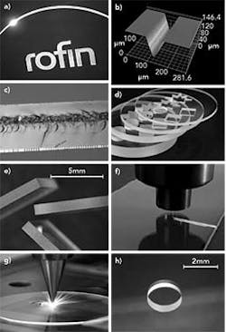
For thousands of years, glass has been a well-known material for a huge variety of transparent or colored products. Today, glass manufacturing comes with significant ecological advantages, benefiting from a basically endless supply of raw material, such as sand, soda ash, limestone, and cullet (furnace-ready scrap glass) and a recycling rate of up to 80% in industrial nations with an effective collection system in place (e.g., Germany). Due to its excellent durability, mechanical strength, and chemical resistance, glass is still a fascinating material used for a myriad of applications (FIGURE 1), although polymers have taken away quite a market share throughout the last 50 years.
To keep established markets and open up new ones, there are development activities at glass manufacturing companies going on right now. One of those is the trend towards very thin glass (20–200µm thickness) for lightweight and flexible products in the consumer products and electronics area. For thicker glass, development groups are continuously trying to increase mechanical strength or to further improve the optical properties of glass products for highly demanding customer applications in consumer electronics, medical devices, and optics, as well as in architectural, automotive, aerospace, solar, and other interesting market segments.
When mechanical or other specific properties of glass are not able to fulfill the requirements of an application, other transparent and brittle materials come into play. Whereas glass has mostly an amorphous structure (like frozen melt), alternative inorganic materials are either made of pure crystals or transparent ceramics. All of these materials have to go through a long manufacturing chain to end up with the desired shape and property; still today, most of the processing steps rely on classic mechanical manufacturing technology to perform forming, scribing, drilling, grinding, or polishing tasks.
Laser processing of glass and crystals has always been quite challenging due to low absorption in the visible and near-infrared (NIR) spectrum and low thermal-shock resistance. The most prominent and "obvious" application is laser marking of glass using the high absorbing wavelength of CO2 lasers. For the last couple of years, a more sophisticated way of surface or glass-inside marking became available on the market—using femtosecond lasers. However, due to the higher price tag of those lasers, applications are mainly found in medical devices or packaging for high-end cosmetics and perfumes.
Many options
Driven by the constant need to reduce the number of processing steps, the amount of waste material, and the use of water in production, the market is strongly pushing laser manufacturers and system integrators to offer alternatives to conventional mechanical technologies. In micro-processing tasks such as cutting and drilling, there is especially a need for more precise and less water-consuming technologies. Various approaches have been taken in the past, with more or less success, to qualify lasers for cutting of glass or other transparent and brittle materials [1]. Those processes can be categorized into:
- Scribe-and-break
- Thermal glass separation by the introduction of a specific stress profile
- Pure laser ablation
- Bottom-up processing
- Glass-inside scribing by an optical breakdown at high power densities
- Classic fusion cutting
- Generation of filaments (e.g., long and narrow modifications) within the volume
Most of these strategies come with one or two benefits, but at the same time also with a long list of limitations. For example, scribe-and-break is an interesting option to mechanically separate thinner cross-sections of brittle materials (less than 0.5mm thickness) after surface scribing with ultrafast lasers. On the downside, it can only be applied to straight lines, runs at low-to-moderate scribing speeds of 10 to 100mm/s depending on the thickness, quite often leaves non-straight edges after cleaving, and comes with a significant difference in bending strength between the scribed side and cleaved side, which could force the manufacturer to trace the orientation. Nevertheless, laser scribe-and-break separation is well established in light-emitting diode (LED) production for sapphire dicing.
Thermal laser separation using a NIR solid-state laser instead of the standard CO2 laser—better known as multiple laser beam absorption (MLBA)—guides a crack from the outside through the material with the help of a laser-induced stress profile. The separated walls show quasi-perfect, micro-crack-free quality, leading to bending test fracture strengths close to the theoretical glass level. But again, there are downsides: it is very difficult to guide that crack around a contour with little deviation from the programmed curve and to close a contour because the crack propagation heavily depends on the existing tension profile in the glass. Recent development activities in that direction include ultrafast lasers to generate a similar effect and edge quality, but contour cutting is still an issue. Therefore, thermal separation sometimes has to be combined with pure ablation, for example, to produce a cell phone display. In this case, thermal laser separation takes care of the straight cuts and the rounded corners are ablated by the use of a high-power ultrafast laser (FIGURE 2).
Pure laser ablation is an option to precisely remove material at the surface or even down through the whole cross-section, thus eventually producing a cut. Drawbacks include the relatively low ablation rate (especially at thicker cross-sections), which results in a typical cutting speed of 1–10mm/s for material thicknesses of up to 0.5mm; the unavoidable taper angle of 10–12°; and the significant heat-affected zones when an ablation depth of 200µm is exceeded. A pure ablation approach can also be used for drilling of glass and other transparent materials, preferably using an ultrafast laser in combination with a five-axis trepanning head to allow for straight drill walls. Still, processing speed in thicker (0.3–0.7mm) material is quite low-on the order of many 10s of seconds per hole.
In the case of pure ablation, the process initiates at the top side of the sample, whereas the laser according to the so-called "bottom-up" processing method starts to disintegrate the transparent material at the bottom side of the work piece and this pulverized material falls out of the ablation zone by gravity. Drill holes with various shapes can be generated by moving the focus up in a continuous fashion. Frequency-doubled nanosecond or picosecond pulses are used at 515–532nm because this process relies on a high transparency for the laser wavelength. Within a processing time of 1 s in 3mm-thick soda lime glass, a 1mm-diameter hole can be drilled and the cutting speed for a free contour is in the range of 3mm/s. Apart from a relatively slow processing speed, some other drawbacks include the facts that strengthened glass cannot be processed with this method and the edges typically show significant chipping in a range of 50–10µm from the processed edge.
Using high power densities often delivered by ultrafast pulses in conjunction with tight focusing down to single-digit microns, an optical breakdown can be achieved in basically any transparent media. By a fast relative part movement and active control of the focus position, a scribe line can be produced within the volume at speeds of up to 1000 mm/s, for example, to dice 100- to 200-µm-thick sapphire LED wafers [2]. The possible material thickness can go down to even 50µm. A mechanical cleaving process is necessary to separate the diced parts. Downsides include the high roughness of the scribed area and the challenge to control the fracture from the center scribe line towards the edges, which can cause uneven cut walls.
Finally, there are two other process approaches that offer an overwhelming number of benefits for mass production of products made from glass and other transparent, brittle materials.
Fusion cutting of sapphire and ceramics
Sapphire is one of the hardest existing transparent materials. Its mechanical and optical properties made it the ideal choice for various components such as cover glasses of watches, displays of mobile devices, protection windows for cameras, or LED carriers. Sapphire cutting with solid-state lasers (for example, lamp-pumped solid-state lasers) has been known for many years and it has become a state-of-the-art industrial process. However, achievable process speed and cut quality are limited, and running costs are relatively high. Recent advances in fiber lasers have brought the thermal sapphire cutting process to a new level of performance [3]. Cutting speed and quality can be significantly improved at much lower running costs.
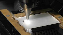
In a thermal cutting process the laser beam is typically focused to a small spot on the work piece. The temperature of the work piece is locally raised above the melting point. At room temperature, approximately 85% of the laser radiation is transmitted through a polished sapphire substrate, approximately 14% is reflected and less than 1% is absorbed to start the melting process. Once the sapphire is molten, its absorptivity rises dramatically and the melt pool can be easily maintained. Therefore, the start of the process (the in-coupling phase) is the most critical part of thermal sapphire cutting (FIGURE 3). Because the thermal conductivity of sapphire is high compared to other glass-like materials, the laser intensities must be very high—usually, intensities of hundreds of megawatts per square centimeter are required to induce melting. Because of the high thermal conductivity, the heat is dissipated rapidly into the bulk material, and there is less risk of local heat accumulation or thermal damage of the bulk material compared to other glass materials.
A process gas jet (nitrogen, compressed air, or in some cases helium) is injected collinear to the laser beam to blow the melt out of the kerf. The gas type itself strongly influences the edge quality of the cut (chemical reaction).
Long-pulse fiber lasers, such as the Rofin-Lasag LFS 150, have become a very powerful alternative to lamp- or diode-pumped solid-state lasers because they can deliver high average and peak power combined with excellent beam quality. Since sapphire and other brittle materials are particularly heat-sensitive, the laser parameters must be carefully chosen and controlled. The position of the focus relative to the sapphire surface is very important to avoid micro-cracks and chipping. An appropriate focal position leads to cuts without any cracks, and edges chipping sizes below 10–20µm.
Because of the nature of a thermal cutting process, the parts can be cut with one single pass. Therefore, cut taper is minimal and can typically be kept below 2°, depending on sapphire thickness. Very good surface roughness values, Ra < 1.5µm, can be achieved. Maximum cutting speed mainly depends on quality requirements and complexity of the parts. Cutting speed results are between 3 and 25mm/s for sapphire thicknesses between 6 and 0.2mm. Minimum kerf width is even below 20µm.
Fiber laser fusion cutting of sapphire and ceramics has become state-of-the-art in highly automated manufacturing processes of components for portable devices (e.g., buttons, protection windows, etc.). If the laser parameters are chosen correctly, the cost-to-quality ratio is unrivaled compared to other cutting processes [4].
Cutting by laser filamentation
A different approach to the technologies described so far has created a huge interest in the market, as the combination of achievable processing speed, edge quality (roughness, straightness, surface damage), material thickness range, and material universality is outstanding.
This new approach is using ultrafast lasers with dedicated properties to create very high aspect ratio modifications in transparent media—the so-called laser filaments [5]. In a simplified picture, filamentation mainly depends on two competing processes. First, the spatial intensity profile of the laser pulse acts as a focusing lens due to the nonlinear optical Kerr effect, causing self-focusing of the beam and a further increase of the power density. At certain peak intensity, low density plasma is created, which lowers the refractive index in the center of the beam path and causes the beam to defocus again. Through the use of a sophisticated optical configuration, the dynamic behavior between Kerr effect self-focusing and plasma defocusing can lead to stable filament formation, extending over several millimeters in length within an optical transparent material. Typical filament diameter is in the range of 1–2µm.
To achieve a basically zero-gap cutting or perforation line, those laser-generated filaments are placed close to each other by a relative movement of the work piece and/or the processing head at typical speeds of 100–1000mm/s, depending on the material thickness and the desired cut geometry.
The Rofin SmartCleave FI filamentation process allows cutting of arbitrary shapes without taper in transparent and brittle materials that are 0.05–10mm thick (FIGURE 4). The resulting surface finish is basically free of chipping. Typical Ra values <1µm lead to high bending strengths of the cut parts. At sufficient internal stress levels that are present in chemically or thermally strengthened glass, the filamention zone separates automatically. Non-strengthened glass (such as—but not limited to—soda lime, borosilicate, and alumino-silicate), sapphire or ceramics can easily be separated by low mechanical or thermal force. The latter can, for example, be provided by a CO2 laser heating process.
The laser filamentation process provides a smart way to cut long and labor-intensive mechanical processing chains down to only a few steps. Applications for the SmartCleave FI technology include mobile phone displays made out of strengthened and non-strengthened glass as well as sapphire; television, computer, and tablet displays; LED and organic LED (OLED) products and other microelectronic applications; glass substrates for integrated circuits; optics; watches; architectural and household glass; medical devices; semiconductors; and ceramics.
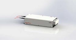
Suitable ultrafast lasers for the filamentation process have been developed, built up as a MOPA chain to allow for very high repetition rates and the patented and exclusively licensed burst mode [6] option, which provides pulse packages with nanosecond separation and programmable power slopes. This, which offers far more flexibility than a regenerative amplifier concept, has been chosen as the preferred design for Rofin's new family of industrial-grade ultrafast lasers (FIGURE 5). Furthermore, the selected Hybrid-MOPA design offers the best of both worlds, combining the robustness, high repetition rate, and beam quality of fiber lasers with the power scalability of rod lasers.
Summary
Processing glass and other transparent brittle materials has always been a challenge for the laser. Many different process approaches have been taken in the past, but most of them were quite limited to a narrow field of applications. Two of those processes have the potential for much wider industrial adoption—laser fusion cutting of sapphire or ceramics using long-pulsed fiber lasers and laser filamentation by ultrafast lasers with dedicated pulse properties.
ACKNOWLEDGEMENT
SmartCleave FI is a trademark of Rofin-Baasel Lasertech.
REFERENCES
1. R. Mayerhofer, "Innovative Laserverfahren für das Schneiden, Bohren und Strukturieren von transparenten und spröden Materialien," Presentation Workshop Glasbearbeitung, Glasstec, Düsseldorf, Germany (Oct. 2014).
2. J. Kangastupa and T. Amberla, "Method and apparatus for processing substrates," patent publication WO 2010/139841 A1 (Dec. 9, 2010).
3. C. Rüttimann, Laser Tech. J., 11, 3, 48–50 (Jun. 2014).
4. C. Rüttimann, N. Dury, C. Woratz, and S. Woessner, "Sapphire cutting with pulsed fiber lasers," Proc. ICALEO, paper M403 (2013).
5. S. A. Hosseini and P. R. Herman, "Method of material processsing by laser filamentation," PCT patent publication WO 2012006736 A2 (Jan. 9, 2012).
6. P. R. Herman, R. Marjoribanks, and A. Oettl, "Burst-ultrafast laser machining method," U.S. Patent 6552301 B2 (Apr. 22, 2003).
Dr. ROLAND MAYERHOFER([email protected]) is with Rofin-Baasel Lasertech, Starnberg, Germany, Dr.ABBASHOSSEINI is with Rofin-Sinar, Inc. (USA), and Dr. CHRISTOPH RÜTTIMANN is with Rofin-Lasag (Switzerland); www.rofin.com.


