High-speed welding of thin Inconel
Laser technology provides a three-fold increase in production while increasing reliability and reducing downtime and operating and maintenance costs
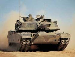
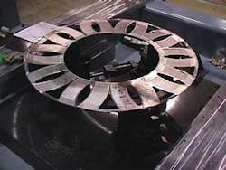
The manufacturing process for the central heat exchanger core in Abrams M1 tank turbine engines requires a considerable amount of welding. These heat exchanger cores consist of stacks of laser welded “A” and “B” plates made of Inconel 625. Each Inconel plate is 0.008 inch thick and has 10 football- and 10 triangle-shaped features that must be precisely aligned with one “A” plate and one “B” plate on top of the other. The plates are then joined together with a lap weld around each feature creating a hermetic seal. Each pair plate (see Figure 1) is then leak tested to ensure all features are leak tight. The inside and outside diameter of each pair plate are then hermetically sealed using resistance welding. The welded pair plates get stacked to a specific height and are welded together to form the majority of the heat exchanger needed in the engine.
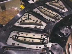
Avco-Lycoming (Stratford, CT) chose laser welding in the mid-1980s due to the fast welding speed, low heat input, low distortion, precision, and ease of automation it provides. Coherent General (Sturbridge, MA) was chosen to design and build Class I turnkey laser cells for this production welding process. To meet the production volume five pair plate welding cells were purchased and installed at Avco. Each welding cell consisted of two 750-watt slow-flow CO2 lasers and two workstations. The laser workstations operated independently with one common load/unload robot system (see Figure 2). A single set of pneumatic clamping tooling was used to clamp each pair of features prior to welding. Once the plates are in the correct location the clamping tooling is raised through the features, expanded, and then lowered, clamping the two Inconel plates together. After each set of features is welded the part is rotated to position the next set of features above the clamping tooling. This sequence is repeated until all five sets of features are welded. To reduce heat input and minimize distortion the welding is done using pulsed mode at a feed rate of 120 in/minute.
In general the machines functioned well and proved to be a very repeatable production welding process. After some years in production however the maintenance required had increased significantly as did the downtime. In September of 1997the machines were moved to their current location at Honeywell in Anniston, AL. Today, approximately 20 years after the initial installation some of the machines are still in production, but maintenance requirements have continued to increase as the systems show their age. Many of the parts are obsolete or repair only. It became impossible to keep all the required replacement parts in stock. As a result, when the systems go down it is usually very costly and time consuming. In late 1998 due to the increasing downtime, escalating operating and maintenance costs, and the demand for increased production volume Honeywell decided to investigate the capabilities of newer laser technology.
During the investigation of new systems it was learned that the original systems could be retrofitted with new (sealed tube) lasers for about half the cost of new systems. The company chose this option, and four new lasers were installed. However, they soon realized this would not achieve all of the benefits anticipated as the attempt to modernize the laser systems and increase productivity actually resulted in reduced throughput.
In late 2002 Honeywell contacted Rofin-Sinar (Plymouth, MI) about replacing the old laser cells with newer technology. An engineering audit of the current systems was conducted to understand all of the process requirements, and to identify attributes of the current systems, as well as changes that were needed to improve performance and reliability. After the initial engineering evaluation was completed an extensive DOE was conducted to quantify the process window using the DC (Diffusion Cooled) Slab laser. The current production clamping tooling was used in the weld development process. The tooling was mounted to the system base while a moving beam system was used to create the weld patterns. The welding speed witnessed, 650 in/minute, far exceeded expectations and the weld quality was very impressive. The welds looked very similar to the current process but the heat input was much less. Several complete parts were welded to verify weld quality, consistency, and to ensure that all welds were leak tight. The welded parts were evaluated using standard production criteria.
It was apparent the high beam quality of the slab laser was a perfect fit for our welding process. The DC020 (2.0kW) CO2 laser with its Gaussian beam quality could achieve weld speeds in excess of 650 in/minute with very low heat input and minimal distortion. The slab laser had several advantages over the old slow flow lasers and the “new” sealed tube lasers as well. One of the benefits is the ability to use longer (200mm) focusing optics; this alone will reduce downtime and consumables costs considerably. The lenses require cleaning regularly and must be replaced periodically due to weld splatter. Plus the slab has no consumables or moving parts in the laser resonator to maintain. Due to the single pre-mix gas cylinder, gas cost is minimal, about $3,000 per year for two-shift operation, considerably less than the older lasers.
After the successful completion of the welding trials and a second onsite evaluation of the existing systems the company brainstormed to develop the system concept and features the new welding systems must have to ensure achieving all of the project objectives. Ultimately Rofin-Sinar was selected as the laser supplier, project manager, and prime contractor for this project and Peco (Process Equipment Company; Tipp City, OH) was chosen as the system integrator to design and build the new generation high-speed laser welding systems.
New high-speed system
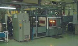
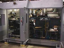
Based on their past experience with linear motor driven gantry systems on more than 1000 high-speed laser cutting systems Rofin chose the linear motor gantry design for the system to take advantage of its high-speed contouring and accuracy (see Figure 3). The systems also utilized a Siemens CNC, a DC020 (2.0kW) CO2 slab laser, an ATFR unit to avoid back-reflection from the workpiece, a circular polarizer, mirror-focus welding unit, stack loader for A and B plates, pick-and-place units, overhead gantry for load and unload stations, an unload chute with conveyor, redesigned two-up tooling instead of the original single station tooling concept, fume exhaust, chiller, and class I enclosure. The two-up tooling concept (see Figure 4) was a direct result of the brainstorming sessions and it has proven to be an excellent choice as it has reduced the cycle time considerably and has resulted in a simpler system design. It is no longer necessary to rotate the part five times to weld each pair of features.
Once the systems were completed and de-bugged, the initial system run-off began. Due to stringent criteria (<1/1000) reject rate, they were concerned about weld irregularities (pin holes) that occurred occasionally in some of the welds. They had not experienced the pin holes during the original welding trials so the team regrouped to determine the root cause so they could be eliminated. Weld samples with grease, various oil, plastic shavings, and various gaps were tested to determine the shape of the weld defects created by contamination and gaps. Using visual inspections the various weld defects were categorized into groups by the shape of the defect. After each group was carefully re-examined and evaluated the team concluded (based on the shape of the weld defects) the root cause of the pin holes was contamination in the weld area. They then contacted EWI (Edison Welding Institute) and asked them to conduct an independent evaluation to determine the root cause. Using visual inspection and cross-section analysis EWI concluded the root cause of the weld defects was oil from the stamping press and foreign debris (plastic shavings) from plastic pallets used to transport the Inconel plates prior to welding. Appropriate steps were taken to minimize the use of contaminated parts and the run off continued successfully. The systems performed very well for the remainder of the 1000-piece run off. With the successful run off complete the systems were accepted and prepared for shipment to the Anniston facility.
When the two new systems were installed at the facility in late 2003 they conducted the second phase of the acceptance, which required a 3000-piece run off. The final run off went well and the systems were accepted and immediately put into production.
Conclusion
Since the installation Honeywell has welded more than 80,000 parts on each system without a single laser failure. Presently the two new systems handle 70 percent of current production volume. Not only is the welding much faster, but also the material handling time has been reduced considerably due to the improved system design. The new systems are very satisfactory and there are no significant issues with either system since they were installed more than 15 months ago. The weld quality and throughput achieved is amazing. Everyone involved with this new process appreciates these machines. The only complaint heard is that the machines weld so fast that system operators no longer have time to read during production.
Not only has the slab laser system provided increased productivity, it has also reduced downtime and lowered operating and maintenance costs considerably. The laser’s higher beam quality allows welding three times faster and has reduced part distortion, which results in a higher quality product. In fact the new systems have been so successful that Honeywell is considering replacing all of the old welding and cutting systems.
Jerry Weatherford, [email protected], is facilities and maintenance leader at Honeywell Recuperator Operations, and Shawn Murphy, [email protected], is a regional sales manager with Rofin-Sinar. This article was adapted with permission from a paper they presented at the Advanced Lasers Applications Conference, ALAC 2004 (www.alac-iluc.org).

