Remote welding impacts auto manufacture
Andreas Korinth and Jim Cann
A laser-based remote welding system (RWS) went into full production at Magna-Autotek in Puebla, Mexico, in October 2004. This RWS uses the beam from a high-powered CO2 laser together with a moving mirror to apply the energy to weld sheet metal components. The advent of high-powered CO2 lasers with excellent beam quality has made this technology feasible for working areas of 1m x 1m or more. The benefits of this process include faster cycle times and smaller “footprint” (plant floor space) as compared to traditional processes. Magna-Autotek is a “Tier 1” automotive supplier and has incorporated remote laser welding into one of the part assemblies that it supplies to an automotive assembly plant.
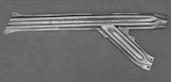
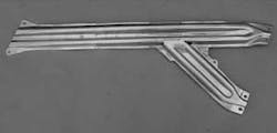
The part for the 2005 Volkswagen Jetta A5 is a door beam impact member assembly consisting of three individual stampings welded together. There are 12 overlap welds on zinc-coated mild steel (see Figure 1). Full production began last October and the forecasted annual volume is 317,000 vehicles per year over a five-year period. Because there are left- and right-hand doors, this gives a total volume of 634,000 impact members per year. Because the Autotek plant runs a two-shift operation, five days per week, this means that the production rate will be 235 parts per hour or around 15.3 seconds per part.
Laser welding was specified in the end customer’s part drawing because it is already in production in Germany, and the plant in Mexico would be assembling a vehicle using the same part. Autotek evaluated both an Nd:YAG laser attached to an industrial robot and a CO2 laser with remote welding to determine the best laser welding process for its application. As noted, this part was already in production in Germany using an Nd:YAG laser and one industrial robot. Autotek made concepts for both processes and obtained capital investment costs by requesting quotes from potential integration suppliers. The following is a summary of the conclusions for this application:
- The investment cost for both systems was similar because two Nd:YAG lasers would be required versus one RWS station. The existing Nd:YAG system requires 24 seconds for one part. Cycle time analysis showed that the RWS could produce two parts in 26 seconds (nearly twice the output). Therefore, full production capacity of 15.3 seconds per part could be achieved with one RWS.
- The RWS has much lower system maintenance costs. The Rofin “slab” CO2 laser requires no optics replacements and only needs a premix gas bottle changed out every eight months. An Nd:YAG laser requires the frequent replacement of lamps, has a higher electrical consumption cost, and the focus optics require frequent changing of the protective “cover slide.”
- The RWS is easily programmed for various weld shapes and weaving functions. This provides greater flexibility to create weld patterns that are custom fit to the part design for better overall weld strength and part rigidity.
- The RWS is available with higher laser powers and fast (50ms) “jumps” from one weld location to the next. This results in much faster cycle times giving flexibility to use the system for other part assemblies in the future.
Based on this analysis, Autotek determined that the RWS was a cost-competitive and more flexible solution for its impact member assembly application.
Remote laser welding principals
In the late 1990s, high-powered (3kW and above) CO2 lasers became available with high beam quality. A typical RWS, shown in Figure 2, includes a high-power (up to 6 kW) CO2 laser and a “remote” scanner system with a long focal length (typically 1000mm-1600mm). A computer-driven motion system plays back a programmed path much like a robot or CNC controller to complete the laser welding of the sheet metal sub-assembly.
The beam scanning motion is based on high-speed linear or “galvo” motors depending on the manufacturer. This enables high speeds when moving from one weld location to the next with move times less than 50ms. The scanner also provides for custom programmable weld shapes (stitches, circles, weaves, and other patterns), which allows the user to apply the best path profile for the particular weld joint.
Comparing welding characteristics
The following is a summary of remote laser welding versus traditional processes to further illustrate the cycle time and floor space advantages of the RWS process:
Resistance welding-A resistance or “spot” weld has the following typical parameters:
- Weld time + movement of the gun by robot ≈ 3-4 seconds
- Can weld 2-3 layers with a typical total material thickness ≈ 2-4mm
- Can weld coated or uncoated steels
- Weld gun acts as a “clamp” and pulls the material together while welding
Arc welding-An arc weld (GMAW) has the following typical parameters:
- Weld speed ≈ 1m/min
- Uses wire feeder to weld 2 layers in various joint configurations (fillet, but, etc.).
- Material thickness is typically 1-3 mm with a total thickness of 2-6mm
- Can weld coated or uncoated steels
- Can tolerate a fit-up “gap” of around ½ the wire diameter.
Laser welding-A CO2-based remote laser welder has the following typical parameters:
- Weld speeds ≈ 3-6 m/min
- Welding time is around 0.2-0.3 seconds assuming a 15mm-long stitch ≈ one spot weld
- Can weld 2-3 layers with a typical total material thickness ≈ 2-4mm
- Can weld coated or uncoated steels, but must accommodate zinc out-gassing
- Requires weld joint fit-up with maximum gaps around 0.1-0.2mm
Cycle time comparisons-As noted above, the welding time for lasers is faster than traditional processes. However, the significant gain in cycle time also comes from the “rapid moves” or repositioning moves between welds. A robot will typically take 0.5-3 seconds to move to the next weld location, while a remote welder takes less than 50ms. When combining the welding and “rapid move” times, we can conclude that remote welding cycle times are around 2 times faster than Nd:YAG welding with a robot and 6-10 times faster than resistance or arc welding processes.
Floorspace comparisons-Because the remote welding process is 2-6 times faster than other welding processes, it will require less plant floor space. This is true because the number of welding power sources is significantly reduced as well as the number of welding stations and transfer equipment. An RWS installation may take up only 25-50 percent as much floor space as compared to other welding processes depending on the application.
Flexibility comparisons-Because there is no actual contact to the part with a weld gun (therefore the term “remote”), the weld station can be easily changed over to a different part simply by changing out the tooling and calling up a different program. This provides the ability to design one station to handle a family of low to medium volume stamped sheet metal part assemblies. Products that have a number of components to be moved in and out of the small working area would require intelligent logistical solutions.
System layout and description
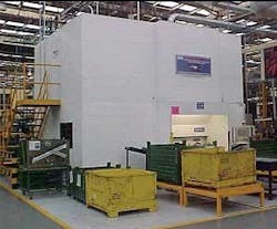
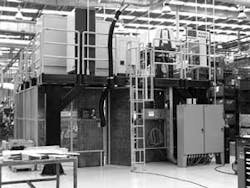
Magna-Autotek decided to be its own systems integrator to have better control over the tooling design and to get a better understanding of the process. The system layout and tooling design was started in June 2003. By December 2003 the system was assembled and the first parts were welded. The laser, scanner box, and chiller are all mounted on the top of the mezzanine to save floor space. Below the scanner box is a turntable with two fixtures mounted on it. This permits the ability to load/unload one fixture while a part is being welded in the other fixture. A stairway allows access to the mezzanine for routine system maintenance. The entire cell must be located on a special foundation to absorb the vibrations of the press shop, which is not more than 25 m away from the laser cell. Vibration measurement is absolutely necessary before installation to avoid big surprises. The floor vibration must be less than the limit defined by the laser supplier. Also an exhaust system has to be considered, because dust and smoke will absorb the laser light.
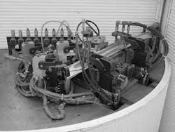
The actual system is shown in Figure 3. The concept is a two-station rotary table that is manually loaded and unloaded. One station has two fixtures for right hand assemblies and the other station has two fixtures for left hand assemblies. The operator unloads the welded assemblies, places them in a crate, loads a new set of stampings, and pushes “cycle start.” The turntable rotates to start the weld sequence and the process is repeated. A partial wall rotates with the turntable to provide a “light-tight” seal during the weld process for eye protection. The entire system is enclosed with a sheet metal cover to create a “Class I” welding system for the safety of plant personnel.
Tooling & plasma suppression-While the remote laser solution offers a faster process and takes up much less floor space, it does have tooling and part fit-up challenges that must be considered. The laser light has no force, unlike spot welding where the electrodes are attached to a gun or cylinder-driven clamping mechanism. As noted earlier, the arc welding process uses wire filler and this allows for a gap in the weld seam. Laser welding is accomplished autogenously, meaning there is no filler wire. Therefore, laser welding requires the tooling to locate and clamp the area to be welded.
In addition, laser welding zinc-coated materials requires a method to allow the out-gassing to vent. Otherwise the zinc will out-gas through the weld creating excessive porosity and blowouts. For zinc-coated materials, the tooling must work along with special part features to provide an out-gassing method.
Regardless of the metal coating (zinc or bare), CO2 welding typically requires a method to dampen and/or blow away the plasma created during the laser welding process. This is because the plasma interferes with the laser beam and can cause the weld process to become unstable or lose the weld completely. The plasma suppression or “shield gas” can be helium, nitrogen, air, or some combination depending on the specific application and laser power. The location of the gas nozzles and sequencing of when to turn them on is also an important consideration for a successful remote welding application.
Autotek designed and built its own tooling. This tooling integrated the need for proper clamping of the part and the need for localized shield gas nozzles. The first prototype tooling was completed in June 2003 and weld development was done at Magna’s Promatek R&D facility in Brampton, Ontario. Autotek is now on its third iteration of part tooling in a continuous improvement of the process. The tooling is illustrated in Figure 4. Note the clamping method and shield gas nozzles located near the weld locations.
Part design-Stamping suppliers that weld using lasers have solved the out-gassing issue by embossing a feature or dimple in the area to be welded. This feature can be incorporated into the stamping die or can be added after the stamping process. The end result is that a gap of 0.1-0.2 mm is created and allows a path for the zinc to out-gas.
Unlike spot welding, the laser weld is very narrow and only requires single-sided access to the part. The remote welder scanning mirror can be programmed to create various weld shapes or patterns. In addition, laser welded parts are stiffer and more rigid than spot welded parts. These concepts must be kept in mind very early in the part design process to take full advantage of laser welding. Weld flanges can be made smaller providing a potential weight savings. Access holes required for many spot welding applications are not necessary for laser welding.
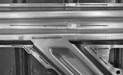
Autotek took these issues into account for this impact member project. As can be seen in Figure 5, there are small, circular “dimples” embossed in the area to be welded to allow for zinc out-gassing. There are 12 “stitch” welds on the part. This provides a solid and rigid assembly.
The tooling and part development for remote welding is relatively new. While standard components were used to build the fixtures, it has taken time and effort to develop the specific techniques for part clamping, application of shield gas, and stamping processes. It is important to provide time for this process development when considering the remote welding process for a new application. For example, air is being used for the shield gas at this time, but Autotek is considering other gasses to increase production rates.
Summary
Autotek is one of the first North American installations of the remote welding concept. The advantages such a system offers include the following:
- Up to 10 times higher throughput as compared to traditional processes
- System layout can be 3-4 times smaller than traditional processes
- Allows greater flexibility on the manufacturing floor
- Part design can be tailored to fit laser welding resulting in lighter, yet stiffer parts.
Autotek has taken the proper approach to implement this process:
- Carefully evaluate the welding options in the early stage of the process and select the most cost-effective approach.
- Take full responsibility for the details of the process to ensure a successful result:
- Review the part design for laser weldability, including the addition of “dimples” to allow gaps for zinc out-gassing
- Design & build the part fixtures to accommodate remote laser welding
- Allow sufficient time for development before production launch
- Early on, define and educate the team members responsible for implementation and operation of the system.
Today, there are a growing number of RWS installations in actual production. While lasers are a relatively expensive welding power source as compared to resistance or arc (GMAW) welding processes, the overall system cost is actually similar and the RWS process offers many advantages.
While this process will not be appropriate for every part assembly, this case study illustrates a successful and beneficial alternative to traditional welding processes. A proper analysis should be done in the early stages of a part design and manufacture cycle to determine if it is suitable for laser based remote welding. In addition, the automotive designer should think about solutions for the component design and assembly to make the manufacturing process easier, faster, and cheaper. The RWS is an excellent welding solution that should be incorporated into this design process.
Andreas Korinth is senior process engineer with Magna-Autotek and Jim Cann is regional sales manager with Rofin Sinar. This article is adapted, with permission, from a paper presented at the Advanced Laser Applications Conference (ALAC 2004).
