Marking implantable devices
A new process enables users to mark parts made of ultrahigh molecular weight polyethylene without using additives or coatings
Glenn Prentice
Ultrahigh molecular weight polyethylene (UHMWPE)-a popular polymer with excellent mechanical, chemical, and wear-resistance properties-is lightweight, low friction, strong, physiologically inert, and electrically nonconductive. These characteristics make this material an excellent choice for fuel storage tanks, guides and fixtures, gears, cutting boards, medical implants, machine parts, and hundreds of other applications. This polyethylene has gained wide acceptance in dozens of diverse industries, including automotive, aerospace, medical, commercial, food, and others. This discussion focuses on the marking of medical implant devices.
Arguably, no other product has stricter controls and regulations than medical implant devices. The Food and Drug Administration (FDA) has stringent material content regulations, requiring rigorous traceability from medical implant manufacturers. While UHMWPE is an excellent material for medical implant devices (shoulder, hip, elbow, finger, knee, etc) it does present problems for permanent marking. Many methods have been used, including mechanical engraving (scratching with some type of stylus by hand), CO2 laser cutting, and several other methods.
Currently, many implant devices made of this material are marked using a beam-steered Nd:YAG laser operating in the near-infrared spectrum at 1064 nm. One method is to simply mark the material with this laser without the aid of any additive or coating. This causes intermittent surface expulsion and inconsistent contrast (see Figure 1).
Another method involves the use of an FDA-approved assist coating or additive. The additive is either an alcohol dispensed pyrolitic graphite or a specialized coating applied to the material. The coating is usually applied to the UHMWPE part using an aerosol spray dispenser or wiped on with an applicator. After the coating has dried, the part is irradiated using the beam from an infrared laser. The beam energy is absorbed by the graphite, causing it to superheat, which in turn causes the polymer in contact with the graphite to melt from the superheated particles. Once the beam has been removed the material cools and the result is an encapsulated graphite particle within the surface of the polymer. After the lasing process is completed the part is thoroughly cleaned of the excess coating. Both marking processes have been approved by the FDA and endorsed by the AMA.
Baublys Control Laser (Orlando, FL; www.controllaser.com) has developed an advanced process of marking UHMWPE parts without the use of additives or coatings. The benefits of this process are both obvious and immediate: increased throughput, cost savings, and improved legibility are among the chief benefits.
At the heart of the process is a TEM00 frequency-doubled, lamp-pumped Nd: YAG laser operating at 532nm wavelength. This laser’s beam is expanded using an upcollimator then adjusted after passing through a collimating lens. (The exact lens configuration is proprietary and crucial to the process.) Optimizing the beam for any abnormalities (such as excessive high energy density) is vital and prevents surface expulsion of the material. This secondary adjustment of the beam expander also corrects for any beam divergence from the laser that may affect the focal position (excessive divergence will affect the state where the focus will occur when passed through a lens). The marking field is approximately a 4 x 4-inch area.
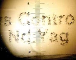
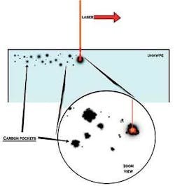
The 532nm wavelength penetrates the surface of the polymer and thermally reacts with the material to create a high-contrast mark (see Figure 2). By varying the laser parameters-speed, power, Q-switch frequency, and beam diameter-it is possible to create a mark or contrast change by controlling subsurface fissures or fractures that produce graphite or char. This char is encapsulated within the material providing a high level of contrast. Variations in the laser power allow for light gray to dark gray marking. The mark is subsurface and can withstand high levels of abrasive wear. Experiments have also been successful with use of a longer focal length lens that provides a larger marking area (see Figures 3 and 4).
To date, this advanced marking process has only been successfully employed using a lamp-pumped laser. Experimentation continues with diode-pumped lasers. However, the divergence characteristics of the diode-pumped laser have proved problematic with this technique.
Learning the techniques of this advanced marking process requires intensive training of the laser operator. Classes are held over a two-day period to instruct the operator how each of the laser’s parameters affect the marking process.
While this advanced marking process was originally developed at the request of major medical device manufacturers, additional processes are being developed for marking Celcon, Delrin, ABS, and several other materials. The potential benefits of this marking system are expected to expand to other industries outside the medical implant. Automotive and aerospace manufacturers have already expressed an interest in the UHMWPE and other material marking processes using the 532nm wavelengths.
Glenn Prentice is product manager with Baublys Control Laser, Orlando FL. He can be contacted by e-mail at [email protected]


