Galvanometer scanning speeds laser processing
Laser materials processing using scan systems eliminates mechanical tool wear and offers flexibility without retooling
Andreas Engelmayer
Over the past 20 years, laser processing systems have found their way into countless industrial applications such as welding, cutting, scribing, engraving, drilling, and marking. Galvanometer scan systems are frequently employed to rapidly and precisely position the laser spot onto the workpiece. Such systems deflect the laser beam in a controlled manner in two dimensions via a pair of rotatable mirrors. The laser beam can be positioned with pinpoint accuracy and specified patterns can be traversed by the beam at defined speeds. The contour traced by the laser spot is determined solely by the scan head’s controller.
Laser materials processing via scan systems offers a number of advantages compared to conventional solutions:
- High dynamic performance and processing speeds
- Elimination of mechanical tool wear
- Contact-free processing
- Small, exactly defined heat affected zones
- Exceptional flexibility without retooling
Applications
Laser marking is a key application for galvanometer scan systems. Laser-marked text is permanent, has good legibility, and requires no consumables. This application is ideal for expiration codes on food packaging or for text on ATM cards and personal IDs.
Scan systems are used in numerous other applications, too, such as high-precision material processing, in the electronics industry (silicon processing, PCB drilling), medical technology (Lasik eye surgery, OCT), rapid manufacturing (stereolithography, laser sintering/melting), and cutting or welding with laser powers into the kilowatt range.
Because of differing requirements concerning laser power, precision, and processing speeds, numerous scan system configurations are on the market. Figure 1 shows an overview of various applications, their requirements, and appropriate scan heads.
Setup
Regardless of the application, laser materials processing systems essentially rely on the following components: laser source, beam shaping, beam positioning, and controller. Additional application-specific components may also be used, such as handling systems, image processors, or process control equipment. The basic scan head system setup is illustrated in Figure 2, and diverse focusing-optic variants are depicted in Figure 3.
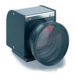
For focusing, a special flat field optic, an F-Theta objective, is typically used and mounted at the scan head’s beam exit. This objective focuses the collimated laser beam independently of the deflection mirror’s position and always within a plane. Such F-Theta objectives are available for a wide variety of wavelengths and focal lengths. The side length of the resulting image field is usually 50-70 percent of the objective’s focal length. Telecentric F-Theta objectives, available for micro materials processing, focus the laser beam perpendicularly to the image field, typically with a side length of up to 50 mm.
The focus diameter is determined by the objective’s focal length, ƒ, and thus the processable surface area, together with the laser type and the scan head’s aperture. For a Gaussian beam profile, the focus diameter, s, can be calculated using the following formula:
whereby λ is the laser wavelength, M2is the beam quality, and d is the beam diameter prior to entering the focusing optics. The factor k accounts for laser beam diffraction by apertures or in objectives. To maximize power density at the focus, and thus processing speed, the beam width should be expanded to nearly equal the scan head’s aperture. In this case, k = 1.83. Typical configurations and their achievable spot sizes are listed in the table.
In some applications, rapidly moving lens systems are placed in front of the scanners for focusing the laser beam by adapting the focal length to the distance between the deflection mirror and the laser beam’s destination point on the workpiece. Such varioSCAN optics are particularly useful when no appropriate F-Theta objectives are available - e.g. for large beam diameters or image fields, high laser powers, or exotic laser wavelengths. Moreover, these varioSCAN optics enable 3D processing within scan volumes and can be used alone or along with F-Theta objectives.
DSP control boards, with on-board memory, function as the hardware interface between the application software, scan head, and laser. These boards synchronize laser control with the scanner movements and implement image correction to ensure that text is precisely positioned without pin-cushion distortion and marked at a constant speed. Third-party software packages are available for many standard laser marking applications.
For micro materials processing, special scan heads are available with precision-optimized dynamics and actively cooled motors and/or electronics to minimize long-term drift. Scan heads from 14 mm aperture can be equipped with supplementary high-precision position detectors for automatic self-calibration.
Innovations
New materials, laser sources, and manufacturing advances will lead to strong growth of scan systems for materials processing.
Next-generation scan systems will feature fully digital control electronics for the scanner motors (see Figure 5). This technology increases processing speeds and enables scanner dynamics to be tailored to specific applications. Optimized parameter sets for particular products or processing steps can be stored and changed via software whenever required.
A further advantage is the ability to monitor the scan system’s status parameters via software, opening up new possibilities in areas such as remote diagnosis and customer support. The scanner’s position and speed can be queried digitally and employed for further processing. This facilitates innovative solutions such as speed-dependent laser control for faster processing and higher quality.
Andreas Engelmayer is in technical sales at SCANLAB AG, Puchheim, Germany. Contact [email protected] or visit www.scanlab.de.


