Diode laser welding of sheet metals
Simple, small, efficient, and easy to integrate, diode lasers may well have an important role in the machine shop of the future
Today’s high-power diode lasers (HPDLs) are small-a 4kW unit is shoe-box size weighing less than 20 kg-and yet they offer certain material processing advantages. The guaranteed lifetime of the diodes is 10,000 hours, but in practice it is usually longer. The only required maintenance are routine changes of water filters and cover glass. Most problems can be fixed via a modem connection to the manufacturer. The efficiency of a diode laser is 4-5 times better than that of a CO2 laser, and the wavelength is typically between 790-980 nm, which means high absorptivity in metals.
The major drawback of this laser, poor beam quality, is caused by its structure. HPDLs consist of several small diode lasers that form laser bars and finally stacks with the output beam a combination of several lasers that are focused to one common focal spot. This combined beam does not, however, reach the beam quality of single laser emitters.
Welding with diode lasers
The minimum focused spot size of an HPDL is larger than traditional welding lasers and it is usually rectangular, around millimeters in size, resulting in a lower power density. Typically the power density of 106 W/cm2 required for keyhole welding is not reached, thus welding usually occurs as a conduction-limited welding process that provides lower and wider welds. The result is an increased heat input followed by a higher level of distortion. The higher absorptivity of this laser, achieved by shorter wavelength, compensates partly for this. Currently industrial diode lasers are available in the power range up to 6 kW, with the highest power density achieved in the power range of 3-4 kW.
There are few studies available about diode laser welding of steels. Optimum beam shape ratio (focal point length divided by the width) is theoretically in the range of 2 when welding in a long direction.1 In the case of a fillet weld in a lap joint, the optimum beam shape ratio should be vice versa.2 Optimum beam shape will give the maximum welding speed or penetration. The characteristic process regimes that change the welding process from heat conduction to deep penetration have been defined and are in the power density range between 1x10⁴ W/cm2 and 2x10⁵ W/cm2. The deep penetration welding process, achieved with the latter value, has been demonstrated with HPDL.1,3,4,5,6 The criteria for deep penetration weld cross section are1: an intense vapor plume above the interaction zone, an aspect ratio (seam depth to width) higher than 1, horizontal dendritic formation perpendicular to weld center line in the seam cross section, and a seam geometry significantly different from heat conduction welding results.
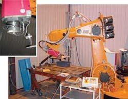
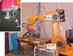
The 3kW diode laser system installed at Lappeenranta Processing Center consists of a Laserline LDL160 3000 HPDL and a Kuka KR 125 industrial robot (see Figure 1).
Welding a butt joint should be performed in the direction of the longer focal point axis and in the case of lap joint, vice versa. The position of the focal spot should always be on the top of the workpiece and in the middle of the joint.
Shielding gas
Shielding gas has a strong effect on the weld penetration of HPDL-welding.7 Welding without any gas shielding has been shown to ensure the maximum penetration.1,7,8
Real-life welding often requires gas shielding, with reasonable welding speed, e.g. to prevent weld corrosion properties. Shielding gas at 25-32 l/min is typically introduced such that the whole melt pool is protected. The development of special shielding gases, ensuring higher welding speed and a non-oxidized weld bead, for HPDL welding has been reported. The addition of active gas shielding causes the melt to flow towards the hot middle point of the molten pool and then downwards, thus bringing more hot metal to the weld root area and deepening the penetration.7 The welds produced with this gas show typical weld properties of deep penetration welding. The use of active gas can also increase weld efficiency and improve economic feasibility.7
When using helium shielding the gas flow must be increased and the welding speed decreased to reach the full penetration.9 Use of a smaller shield gas tube diameter can increase the weld speed and decrease gas flow because the gas deflects the plasma cloud and decreases the oxidation level while still providing adequate protection.
Bead-on-plate welding
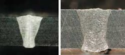
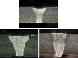
Bead on plate welding experiments show that diode laser welding is a fast welding process when the material is thin. In Figure 2, the maximum welding speed decreases fast with an increase in material thickness. The effect of material thickness is similar with all power levels. Cross sections of welds show high depth/width ratio, almost two-dimensional head conduction. In case the heat input is too low with non-complete penetration, the heat conduction is three-dimensional. Some bead-on-plate weld cross-sections with acceptable weld quality are shown in Figure 3.
null
Fillet weld
The fillet joint in lap joint configuration is typical for thicknesses less than 2 mm where the weld requirements are set by application rather than material thickness and the welding speed to achieve quality welds varies.
A shallower impingement angle makes it possible to reach much higher welding speeds, as shown in Figure 4. The joint geometry also changes with the beam pointing position. The melting of the outer corner of joint depends on the power distribution.
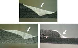
In welding of T-fillet joints, diode lasers provide good joining between parts with the wider penetration actually lowering the position tolerance in comparison to conventional keyhole welding. The problem is that low penetration sets the limit for maximum weldable weld size.
Butt joint
The diode laser welding speed is considerably higher for butt joints compared to bead-on-plate (approximately 5-35 percent, depending on the width of an air gap). The joint can be prepared using most pre-preparation techniques.
When welding 3mm sheet the welding speed with a focal length of 200 mm can be 50 percent lower than the speed with focal lengths of 100 mm (see Figure 5). In thick sheets an air gap in the butt joint can ensure 4-15 percent higher welding speed compared to a joint without an air gap (see Figure 6). The maximum welding speed in 4mm-thick sheet (focal length 100 mm) can be increased by 7-20 percent with an airgap.9 The process tolerates gaps as wide as 0.2 mm in 3 mm material thickness. Even though HPDL welding of a shear cut edge is possible there may be lack of material because of too wide an air gap and bent sheet edges.
The weld process together with weld cross-section analysis and the utilized power intensity (>4x10⁴ W/cm2) fulfills the three criteria given for deep penetration welding. This means that with a suitable arrangement the deep penetration welding process can be established with current high-power diode lasers. The narrow airgap in the joint makes the establishment of this process easier.
The high welding speed reached with the butt joint is achieved because the joint itself has a small air gap enabling part of the beam to penetrate deeper into the joint. Actually, a narrow air gap enables an increase in welding speed. In case of shear cut edges, the bent edges that form the joint actually guide the laser beam efficiently into the joint. In butt joint welding the process may be conduction limited, but the laser beam can enter deeper into the joint via the gap causing the absorbing surface to be in the vertical direction such as in keyhole welding. The weld cross sections give the indication that the welding process has been deep penetration welding.
Effect of beam impingement angle
Experiments show that the process is quite tolerant of changes in the beam/material interaction angle.9 Angles of 10 degrees in drawing position can ensure higher welding speed for a certain configuration. For example with 4 mm thickness, the drawing beam impingement angle of 10 degrees shows 0.1 m/min, a 25 percent higher welding speed.10
The welding process is tolerant to the angle of incidence and therefore has more certainty for industrial applications. To maintain an optimum speed in three-dimensional welding the robot or the workstation controller must tilt the laser welding head in advance of reaching a corner. The HPDL welding process can tolerate at least ±10 degrees change in incidence angle thus enabling easier utilization of the process.
Conclusions
The diode laser is a unique laser tool: simple, small, efficient, and easy to integrate. It has very high efficiency in converting electricity to optical power. The only problem is poor beam quality. The future goal is to reach smaller focal spot size, higher power density, and more homogenous power density.
There are some reported industrial applications of diode laser welding of thin sheet2,11,12,13 and other processes like surface treatment.9,13 Diode lasers may have an important role in a machine shop of the future.
High-power diode lasers were tested with various joint configurations and the experiments showed the process is fast for butt joint applications. The drawback of a large focal spot offers some advantages compared to keyhole laser welding. It makes it possible to use an industrial robot for the welding workstation, making it possible to utilize the other advantages offered by a normal industrial robot. Research in the future will concentrate on the effect of a shielding gas.
Antti Salminen is with Lappeenranta University of Technology and Veli Kujanpää is both with Lappeenranta University of Technology and VTT Industrial Systems, Lappeenranta, Finland.
References
- Petring, D., Laser Magazine, Sept. 1999, p. 31.
- Salminen, A., Jansson, A. and Kujanpää, V., Proc. Int. Conf. Photonics West 2003: High-Power Diode Laser Technology and Applications, 25-31 January 2003, San Jose, California, USA, SPIE Vol. 4973, ISBN 0-8194-4773-0 b. June 2003, 12 p.
- Petring, D., Benter,C. and Poprawe, R., Fundamentals and Applications of Diode Laser Welding, Fraunhofer-Institute for Lasertechnology ILT Aachen, Germany.
- Gillner, A., Loosen, P., Petring, D., Wissenbach, K. and Poprawe, R., Proc. ICALEO 99, San Diego, USA, Nov. 1999, LIA Vol. 87, pp. A12-A22.
- Abe, N., Higashino, R., Tsukamoto, M., Noguchi, S. and Miyake, S., Proc. ICALEO 99, San Diego, USA, Nov. 1999, LIA Vol. 87, pp. A236-A244.
- Bliedtner, J., Müller, D., Wolff, D., Heyse, T., Jahn, D. and G. Michel: Laser-Praxis, Hanser Verlag, März 2000, p. 31-35 Dresden.
- Berkmanns, J., Danzer, W.; Härtl, J.: Proc. Int. Conf. ICALEO 2002, Phoenix 2002, Laser Institute of America, 10 p.
- Kujanpää, V., Maaranen, P. and Kostamo, T., Proc. Int. Conf. On Laser advanced materials processing LAMP2002, May 27-31 2002 Osaka, Japan Laser Processing Society, 10 p.
- Salminen, A., Fellman, A. and Kujanpää, V., Proceedings of the 23rd International Congress on Applications of Lasers & Electro-Optics ICALEO 2004, October 4-7. 2004. San Francisco, USA, Laser Institute of America, 8pp.
- Salminen, A., Siltanen, J., Jansson, A. and Kujanpää, V., Proc. Int. Conf. ICALEO 2003, Laser Institute of America, Jacksonville, October 13-16. 2003, Paper 205, 10 pp.
- Bonss, S., Seifert, M., Barthel, K., Brenner, B. and Beyer, E., Proc. of 20th Int. Conf. ICALEO’2001, October 15-18. 2001. Jacksonville, USA, Laser Institute of America, 10p.
- Salminen, A., Proc. Int. Conf. On Laser advanced materials processing LAMP2002, May 27-31. 2002 Osaka, Japan Laser Processing Society, 10 p.
- Hovikorpi, J., Jansson, J. and Salminen, A., Proc. Int. Conf. Photonics West 2003: High-Power Diode Laser Technology and Applications, 25-31 January 2003, San Jose, California, USA, SPIE Vol. 4973, ISBN 0-8194-4773-0 b. June 2003, 12 p.
