The big engine that can

A turnkey laser workstation marks 200-pound locomotive cam gears
David A. Belforte
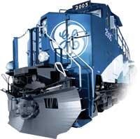
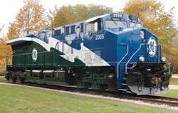
GE Transportation Rail is a global technology leader and supplier to the railroad, transit, marine engine, and mining industries. The company, with plants in Western Pennsylvania, has been the market leader for diesel-electric locomotives for the past decade and currently more than 15,000 GE locomotives are in service worldwide, pulling both freight and passenger cars.
Railroads are no different than any other business; the road to profit lies in maximizing output for minimal investment. From the beginning railroads have striven to move their consignee’s products as economically as possible. This has meant a search for faster, higher horsepower and more economic motive power. The so called “horsepower race” actually started back when railroads were brand new.
Early locomotives were mostly steam powered. Wood, coal, or oil was burned to heat water in a boiler and produce steam, which powered a piston connected to a drive rod, which turned a wheel. Over the years many variations of this theme were produced, culminating in massive locomotives with many coupled drive wheels to maximize the tractive effort of all this horsepower. These machines had become highly specialized maintenance nightmares. By the 1930s and 1940s it was felt that steam power had reached its maximum return for investment.
Early in the 20th century it had been discovered that electric traction was a much more efficient method of propulsion. But this required the construction of stationary generators and an overhead infrastructure to transmit the electric current to a locomotive. The electricity was used to turn a (traction) motor, which was geared to an axle. Motors could be mounted on every axle of a locomotive, allowing higher horsepower tractive effort to be applied to the rails using less electricity.
Many inventors and manufacturers had been working for years on alternatives. The development of the lightweight, high-horsepower, diesel engine was the answer. This allowed manufacturers to couple them with a generator to drive the traction motors, right on board the locomotive. This eliminated the expensive fixed plant previously required for electric traction.
GE had been a supplier of electrical components to the manufacturers of true electric locomotives. Early diesel electric locomotives required much of the same equipment. The company worked in partnership with several locomotive builders to increase the capacity of the electrical equipment and keep pace with the increases in diesel horsepower. GE also built its own line of smaller switching and industrial locomotives to fill a niche market.
Through the 1940s and 1950s the North American railroad industry converted to diesel electric motive power. Diesel electric locomotives became less costly to maintain, more flexible, required less downtime, and were capable of being connected together and controlled from one location. This last trait was the nail in the North American steam locomotives’ coffin. Now a single engineer could control enough horsepower and tractive effort to haul trains that would have previously required two or more steam locomotives, each with its own crew.
The 1950s and early 1960s saw a decline in North American locomotive manufacturers, even as railroads were clamoring for higher horsepower. GE capitalized on its experience with locomotive electrical controls and started manufacturing its own line of higher horsepower locomotives in the early 1960s. The Universal series of locomotives set a new horsepower standard for the industry. In the 1970s fuel economy became more important than horsepower, and GE stepped up to the plate again. In the 1980s advances in electrical controls allowed the horsepower race to escalate again. GE had always been on the cutting edge of electrical control technology and was able to take advantage producing “second generation” diesel electric locomotives that established a record of improved performance, reliability, and life cycle costs. GE had become the number one producer of high-horsepower diesel electric locomotives. But this was not the pinnacle for GE.
Up until this time most diesel locomotives had been powered by DC traction motors. DC traction was reasonably efficient, easily maintained, very safe, and only required a generator to produce current. However DC traction motors have an efficiency curve that drops as their RPMs decline. The slower they turn the less efficient and more overheated they become.
The slower a locomotive wheel is turning the higher the requirement for tractive effort. Locomotive horsepower is required to peak at the slowest “stall speed” the traction motors can produce. Adhesion improvements through the 1970s and 1980s had brought this “stall speed” down to about 8 to 9 MPH. At this speed the traction motors would be at their maximum horsepower and lowest efficiency. Any lower speeds were limited due to damage effects caused by overheating and lost efficiency. Railroads and industry suppliers had always known AC motors had a much better efficiency curve, but had not been able to economically control AC current in a motive situation.
In the 1990s computer controls and AC technology advances developed for the European railroad markets were found to be adaptable to North American railroad requirements. GE was able to marry this AC technology to a new generation of super efficient high-horsepower diesel engines and alternators to produce today’s cutting edge locomotives. In some ways these locomotives’ performance gets better the slower they move. High-speed efficiency is also markedly improved. Today GE continues to innovate and improve its current family of AC, DC, and passenger locomotives.
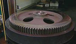
About two years ago the company began to look for a means of improving the way incremental timing marks were made on large, 200-pound, locomotive cam gears at its Grove City, PA, plant. At that time it was using an old laser marker that was cumbersome to work with, problematic to operate, and that produced inconsistent marks.
A timing mark is a line etched by the laser at every degree point going 360 degrees around the camshaft gear. It is used to set the timing of the valve train to the crankshaft so that the valves begin to open as the piston reaches “dead top center” of its travel in the cylinder. This happens during both the intake and exhaust cycles of the 4400-horsepower, 16-cylinder engines. The cam gear is bolted to the crankshaft-driven camshaft, which drives the valve train. The cam gear is also used to set the engine timing by its degree alignment with the crankshaft gear.
Timing marks are generated by the laser engraving into the steel surface a hash mark for each degree and numbers at every 10th degree from 0 to 360 degrees. So there are 360 hash mark lines and 36 numbers to be laser etched.
GE found the reject rate on parts marked by the old laser was about 50 percent, which resulted from lack of repeatability in the laser’s output as well as inconsistencies with the workstation caused by inaccuracies in the handling of the 200-pound gears. Improper marks had to be ground off by the system operator, and the gear was then remarked.
Telesis Technologies Custom Engineering (Circleville, OH) was approached and, after reviewing GE’s needs, proposed an easy-load Eclipse Laser Marking System with CDRH Class I enclosure that utilizes an indexer mounted on a linear slide. The large cam gears could easily be loaded by crane onto the indexer, such that by pushing a button, the complete table slides the cam gear into a Class I, interlocked enclosure, initiating the engraving of the 360-degree timing marks on the gear face. Previously, the operator had to lift a metal hood and “walk” the large cam gear into it’s mounting fixture while still hanging off the crane without damaging the laser galvo head on the old system. The Telesis system is an easy load with no obstruction thanks to the sliding rotary table. The system also includes light curtains for safety, and the cam gear fixture provides an easy reference to make sure the gear is in proper orientation.
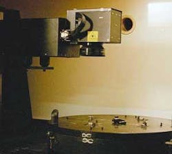
The Telesis system that GE purchased has the capability to mark both cam gears and engine plates, depending on the fixture setup. This arrangement was chosen because the production rate for locomotives is low, and by taking advantage of the laser’s flexibility the company can mark both gears and engine identification plates on demand. The engine plates are marked in batches from barcode-generated information while the gear marks use static information. The system that is currently in use is powered by a 100W lamp-pumped Nd:YAG laser.
The custom workstation was designed to mark gears in automatic mode and plates in a manual mode. A pushbutton station and mode selector switch controls movement of the horizontal slide mechanism and the laser’s energy to the station. The side-loading feature that allows plate marking was not available on the original laser marker. Because the application required a rotary table to enable marking around the total circumference of the cam gear, this adds the benefit of handling multiple fixtures when the need is for identification plate marking. The side access door provides not only the means for set-up on the cam gear application, but also is the load/unload station for the plate marking.
In addition, the Telesis AMI (Automatic Machine Interface) software allows ease of programming and barcode scanning for pattern load, and scanned information goes to the proper fields. The AMI also loads a picture file of the correct tag to be marked so the operator is assured of proper pattern loading, fixturing, and so on. Because the Telesis software can support four programmable axis controls, the operator simply loads the correct pattern for cam gear or plates and the rotary table, slide, and programmable “Z” tool post move into place for the application. The ease of programming and operation has brought a total operator acceptance of the system and reduced the learning curve to a minimum.
GE installed this system about 18 months ago and the results to date have been exceptional. As of April more than 1800 camshaft gears had been marked with zero rejections. This is especially important because each gear is checked with a test fixture to ensure that individual hash marks are in correct alignment and are repeatable around the 360-degree marking of the gear. The production savings in not having to regrind and remark has already met the return on investment in the short 18 months the system was in operation.
The operation sequence for gear marking is as follows; the operator manually loads and aligns a gear in the fixture and when they are clear of a light curtain the operator receives a ready signal to run the gear program on the PC. The gear is moved into the laser enclosure and when in position the door is automatically closed and the laser makes the required marks around the perimeter of the gear. Upon completion of the marks the door opens automatically and the gear is withdrawn from the Class I workstation.
For plate marking the slide is automatically moved into the marking location by scanning the barcode, which selects the proper pattern and sets the “Z” height of the laser to proper focus. The operator manually loads single or multiple plates into a fixture slot through a side door. When the door is closed and “start print” is enabled, the software rotates the fixture to align the plate to the laser beam and performs the required marking. If multiple fixtures are used, the software will drive the rotary table to mark the next batch of plates until the complete pattern is marked on all quadrants of the table.
Perhaps most impressive is the ability of the Telesis Nd:YAG 100W Eclipse Laser Marking System to remain stable throughout the process of the depth required for the camshaft marking and the surface annealed mark needed on the plates. The dual-process Telesis system has met the same GE commitment to imagine and build innovative solutions that benefit its customers.
Major contributions to this article were made by Steven Belforte, assistant director train operations, Guilford Rail Systems, and Ralph Villiotti, eastern regional sales manager with Telesis Technologies Inc. (www.telesis.com).