High speed balancing with fiber lasers
Marek Mamczur and Jack Gabzdyl
Reduces spindle balancing time by 80%
Today’s high speed production drills in printed circuit board (PCB) manufacture operate at speeds in excess of 250,000 rpm. The balancing of the spindle shafts in these devices needs to be manufactured to high levels of precision. They must be individually fine tuned by very selective removal of material to ensure that, in operation, they run true. Any eccentricity in rotation can cause drill bit wobble, which results in breakage and unwelcome downtime. Current manufacturing methods are somewhat arcane and use skilled labor to remove material through grinding – a manual and laborious task that frequently needs iterative attempts to optimize balance.
Using proprietary software in conjunction with a 40 W pulsed fiber laser, the material for removal can be identified and then accurately removed through a laser milling process while the spindle is still rotating. This process has had a dramatic effect on throughput and efficiency, resulting in an 80% reduction in balancing time and a 20% increase in yield that used to be due to errors made by the man in the loop process.
Balance accuracy is down to hundreds of micro-grams, and shaft runout (TIR) can be reduced to less than 500 nm.
Introduction
Lasers have been used for micromachining for over 30 years as the flexibility and level of control offered has shown itself to be ideally suited to a growing range of applications. Control of laser parameters can give precise material removal with high quality finishes. The introduction of fiber lasers has offered end users competitively priced, compact, and reliable solutions that are virtually maintenance free.
In PCB manufacture, there is a growing requirement for the incorporation of microvias. These are extremely fine holes, currently down to 75 µm diameter (current standard), and are typically manufactured with high speed mechanical drills. Laser drilling of via holes is also a recognized process, but in this application both technologies have wide followings. Some of these drills operate at speeds in excess of 250,000 rpm, requiring extreme rotational stability from the electro-mechanical spindles. To achieve these rotational speeds, the spindles need to be extremely finely balanced.
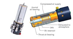
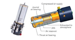
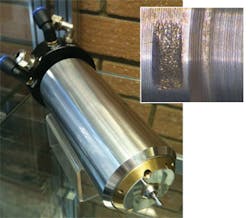
As the world’s only volume spindle supplier, Westwind has established an extensive range of proven PCB spindles, many of which are recognized as the industry standard. Due to the ever-increasing demand for smaller hole sizes in drilling, they are continuing to develop their spindles for higher speed. Key to these developments is the accuracy and repeatability of spindle balancing (FIGURE 1).
Dynamic Laser Solutions, a UK-based engineering solution provider, working with SPI Lasers, has produced an automated laser-based spindle balancing system that has significantly reduced total part balance time, minimized part rejects and improved balancing tolerances.
Existing manufacturing processes
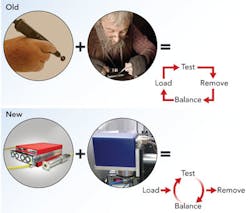
Conventional manufacturing methods for spindle balancing require skilled labor. Each spindle is individually balanced and adjusted by means of manually grinding away micro-grams of material from specific locations on the spindle using a grinding disk. This is a highly skilled operation requiring a steady hand and considerable experience. Once the spindle has been adjusted, it is re-tested and the effectiveness of the adjustment assessed. This tends to be an iterative process requiring multiple grinding operations before an acceptable tolerance is achieved, and, in the worst case, can lead to a part that has had too many adjustments to be acceptable and becomes scrap.
Laser balancing process
The challenge of producing a turn-key system is dual-fold. First, understanding how much material and where it needs to be removed, which is an extension of existing technology, and second, effecting the laser micromachining (FIGURE 2) to remove the material from the specified location. Ideally, this would be done in a single operation, eliminating the test – unload – adjust – re load – retest cycle!
To assess the balance of the shaft, it is spun in a custom jig at 18,000 rpm. The eccentricity of motion of the spindle is measured by two accelerometers used to measure the force vectors, a capacitive sensor to measure the air gap to the shaft and an optical sensor to monitor the rotational position of the spindle. A simple marker pen mark on a small shaft in the collect is sufficient to enable accurate location of the angular position of the shaft that is used as the datum for measurements and subsequent material adjustments.
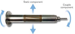
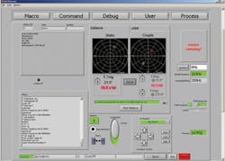
The dynamic instabilities of the spinning spindle are highly complex and need to be accurately analyzed and de-convoluted into simple vectors that can be used as the basis for making adjustments (FIGURE 3). The motion vectors are derived from the accelerometer and capacitive sensor readings. The internal software, based on complex algorithms, separates out the motion into its static and couple components. The software also calculates the balancing adjustments required in terms of position and mass of any mass that needs to be removed (FIGURE 4). This has some significant constraints in that material can only be removed from very limited and specific locations on the spindle, and all this is taken into account in the software.
Once analyzed, instructions are given to the laser micromachining system to make the required adjustments. This production system comprises a scanner with 10 mm aperture and a 100 mm F-Theta lens coupled with a SPI 40 W HM pulsed fiber laser. A number of lasers, both CW and pulsed, were evaluated prior to selection of the 40 W HM model. The decision was based on the removal rate and the quality of part (post processing), with the optimized conditions being 30 kHz pulse repetition rate, 1.25 mJ pulse energy, >20 kW peak pulse power, and 200 ns pulses (full pulse length). The whole scanner assembly is mounted on an X-axis gantry to give the system the capability for lateral motion so that the spindle can be optimally located below the scanner. This also enables multiple spindle balancing stations to be set up, allowing spindles of different diameters to be processed as each spindle size requires its own jig.
The jig was constructed as an open cage arrangement such that some access to the rotating spindle was available in-process. Locations and areas on the spindle where material can be removed while spinning is very limited, but sufficient to meet the balancing requirements. To make couple compensations, mass is removed from locations at either end of the spindle, while for static, the material is removed from two locations on either side of the copper motor windings. The laser and scanner are centred on each individual area for processing so that operation is restricted to the center of the scan field. The material is removed over a specified arc centred on the point identified by the system. The firing of the laser is coordinated with the rotation of the spindle so that material removal can be achieved on the fly. Slight lateral motion is also used, with the scanner broadening the removal area (FIGURE 5).
Material removal volumes are extremely small – just a few milligrams – and hence laser processing time is relatively short; just a few seconds per location is all that is required. Once the micromachining process is completed, the spindle eccentricity is re-measured and, if required, a second balancing iteration is performed.
Conclusion
The implementation of laser machining for spindle balancing has been demonstrated in an industrial environment. Initial results have shown the system is capable of reducing balancing time by 80% and increasing spindle yield to >99.95%. Further processing developments to eliminate burr formation, based on the use of different pulse durations using the waveforms available of the SPI laser, are being undertaken in an attempt to improve quality further without affecting cycle time. The significant benefits shown in terms of productivity and accuracy mean that laser balancing may become the norm for future spindle manufacture.
Acknowledgment
The authors would like to thank Westwind for its permission to publish this work.
Marek Mamczur is managing director at Dynamic Laser Solutions, and Jack Gabzdyl ([email protected]) is product line manager at SPI Laser.
More Industrial Laser Solutions Archives Issue Articles
