Laser returns to the railway industry
An integrated application for cutting and welding
Antonio Vendramini
In Italian company, Tube Tech Machinery, gives credibility to laser for railway industry applications for one of the world's largest manufacturer of passenger and freight cars for Indian Railways.
Ever since the laser's origin, it has been considered a means to solve the issues of heavy industry, which experienced difficult economic conditions after its widespread use in providing goods and services through the post-war years. Laser technology enjoyed success, taking advantage of the opportunities provided by CO2 sources with the development of multi-kilowatt power units. Thus, it is not surprising that, at the end of the 1970s, Italy, one of the first countries in Europe to understand the great potential of this extraordinary tool, was the first country to install two 20 kW CO2 sources. Their purpose was to investigate the possible applications of welding gears in one of the first laser applications in the automotive industry, made at FIAT Mirafiori, to weld gearbox synchronization units and in heat treatments.
It took approximately 10 years to show that this would not be laser's main application, which instead was to be found in the thin metal sheet-cutting sector, and to a lesser extent in welding applications, where the high power laser was used in large-scale industries and where the relatively high investment cost of laser systems could be absorbed by the large number of applications. This is why, after cutting and welding applications were proceeding in the automotive industry, that the transportation industry thought it was the turn for railway vehicles to use these application. However, this did not happen because, in this sector, dedicated cutting and welding systems had to be used; there were no ready applications because it was difficult to handle two processes that required different operating conditions with one single system. This has led, in the past few years, to a greater development of laser technology in the shipbuilding industry to weld the metal sheets composing the decks with vertical reinforcements, but laser did not develop in the railway industry.
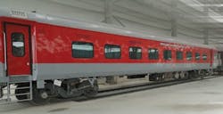
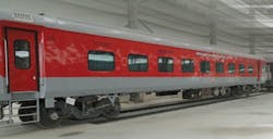
However, a major step in developing laser technology in the railway industry occurred at the end of 2011, when the Italian company, Tube Tech Machinery srl [Cazzago San Martino (BS)] introduced its system for laser cutting and welding rail coach roofs and side walls. This system was put in use for Rail Coach Factory, an Indian coach manufacturing unit of the COFMOW (Central Organisation for Modernisation of Workshops) group, which manufactures passenger and freight vehicles for Indian Railways. This company is one of the world's largest in the railroad industry, managing over 60,000 km of railway network and transporting over 18 million passengers and 2 million tons of goods every day. This system is the first truly integrated laser application in the railway industry.
The system
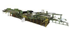
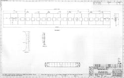
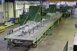
"The TSL(Talia e Salvatore - Laser Cutting and Welding) 2.5-25 system has been designed to create large metal sheets (2.5 m width by 25 m length) not available on the market by laser welding together 2500 x 2000 mm sheets, which have had their edges trimmed by laser cutting before being welded," says Marcello Filippini, Tube Tech Machinery's CEO. "These welded sheets, mainly made of stainless steel with a thickness usually below 3 mm, are the base for railway vehicle's side walls and roofs. The system can also create, through laser cutting, all the openings for doors, windows, and ventilation compartments that define a complete structure for the side walls and roofs of the car. As shown in FIGURE 1, this is large-sized and very complex. However, once in operation, this complexity seems to disappear, and the system automatically carries out with simplicity all the operations to manufacture a side wall 18 m long with 19 openings for the windows, as shown in FIGURE 2."
The step-by-step process
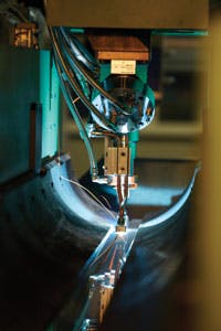
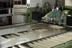
Filippini explains the manufacturing process: "A suction cup unit picks a single sheet from the pack and places it on the feed table, where it is centered in the two orthogonal directions and gripped at the bottom by grippers that push it towards the central platen, along which the cutting head and the welding head slide alternatively."
When asked why were two heads preferable when devices suitable for both processes are available on the market, the reply is prompt: "We knew that; nevertheless, we preferred choosing a more complex solution that could ensure higher performance for each application. Indeed, multi-purpose heads simplify the system, but they partly penalize both applications. This is why we have opted for greater complexity, in terms of the system, to obtain better operating conditions both for laser cutting and welding. Plus, we need to bear in mind that, at this point, cutting operations consist of trimming and, to prevent the formation (even locally) of burrs, we had to use a capacitive sensor that follows even the slightest corrugation of the sheets. This would not have been possible with a focusing head that also allowed for welding operations."
He continues, "We have two sheet pressers in the work zone: the one near the loading zone has controlled movements in the direction of the major axis of the system, whereas the other has only vertical locking action. The rear edge of the sheet is firmly locked by this second sheet presser and is trimmed using the laser. Meanwhile, the system feeds the second sheet, which, once centered and aligned, is locked in the front part of the moving sheet presser. The laser carries out a new trimming operation. Then the sheet presser moves this second sheet next to the first one and the laser beam welds the two sheets together." See FIGURE 3.
Technological refinements
Filippini continues, "Upon customer request, the system makes use of a 3 kW diffusion-cooled CO2 source (Rofin DC030); however, given the reduced thickness of the sheets, they could have used a fiber laser." The described operation is repeated N times until reaching the required length of the sheet. Filippini points out that "on this sheet, you can also make the openings for doors, windows or other penetrations. This process is carried out using the same cutting head that had previously performed the trimming operations, and it is the CNC-controlled platen that moves longitudinally along an 8 m length. This implies that, once 4 sheets have been welded together, the process is interrupted to allow cutting out the openings in an 8.0 x 2.5 m work area."
To guarantee the same cutting conditions in every point of the work zone, Tube Tech has inserted a flying mirror device called a trombone along the optical path of the beam. The sheets are fed on motorized rollers to protect these rollers from molten material during cutting operations while the openings are being cut out, and the sheet is supported by a "fakir's bed" with movement cylinders that lower down. Each one of these is protected by a sheet to prevent them from being hit by jets of molten material that can scratch the sheet they are meant to feed. Because the system automatically manufactures the side wall or the roof of a rail coach, the burrs of the cut are further chopped by laser cutting and are discharged between the tips of the fakir's bed that supports the sheet. These pieces are collected by a conveyor belt that slides under the system along its entire length. The larger pieces are collected by a carriage with suction cups located in the front part of the platen that moves the two focusing heads, as shown in FIGURE 4.
From this simple description, the reader can imagine, on the one hand, the complexity of the TSL 2.5-25 system and, on the other, its great operational simplicity as a result of its accurate design that has taken all the possible complications related to automate processing on large metal sheets into account. The sheets, welded together, onto which openings have been made, were pushed by the same grippers that picked the first sheet of the pack and that the laser, besides cutting out the openings, also carries out the longitudinal trimming of the sheets welded together.
"As you can see in the drawing of a generic rail coach side wall in FIGURE 2, in most cases, the edges of the windows must be deep drawn," Filippini concludes. "Of course, this operation cannot be carried out in line on the TSL 2.5-25 unit, but it requires the group of sheets to be automatically discharged and then repositioned on the line. This operation is carried out by a cantilever system that supports a group of suction cups, each of which can be automatically deactivated to prevent them from falling inside an opening." (See FIGURE 5.)
"Tests have been carried out by Rail Coach Factory on the sheets processed by the TSL 2.5-25 system. All the laser welds carried out with the system have obtained the Indian Railways' certification upon undergoing a strict series of tests: traction, bending, fatigue, abrasion, mechanical, and corrosion resistance."
Dr. Antonio Vendramini ([email protected]) is a well-known international consultant on industrial laser material processing, a prolific author and contributor to his own publication, Applicazioni Laser, and to Industrial Laser Solutions. His company, Lasertec s.a.s, is located in Segrate, Italy, near Milan.
