Advances in laser drilling of turbine airfoils
Experiments with some of the new laser drilling technologies have resulted in enhanced process sensing and control, such as breakthrough detection
Todd J. Rockstroh, Doug Scheidt and Clarence Ash
GE Aircraft Engines (GEAE) has investigated the specialized pulsing features of commercially available pulsed Nd:YAG solid-state lasers. The focused pulse energy can be delivered to the target/turbine airfoil in short bundles on the order of 0.2 millisecond or less. These short pulses or pulselettes, delivered at relatively high-frequency bursts within the conventional multi-millisecond envelope are shown by the authors to provide unique drilling capability. Short-pulse drilled holes are of higher quality (reduced recast and collateral damage) and the smaller pulselettes energies can be utilized to minimize or eliminate internal beam blockers.
Current applicationAs shown in Figure 1, a turbine airfoil is filled with a suitable beam blocker such as wax, ceramic beads or other fluids to prevent internal damage once the laser beam penetrates the airfoil wall. The external surfaces are coated with grease, paints, milk of magnesia and various compounds to prevent debris from splat quenching on the external surfaces. Laser drilling is applied to turbine airfoils in order to minimize the cost of drilling and enable shallow angles of attack for film cooling.The cooling air from these holes is used to create a cold film layer across the surface of the airfoil and prevent hot combustion gases from directly contacting the airfoil. The cooling air comes from air taken in at the front of the engine, thus adding to drag and reducing fuel efficiency. As noted, lasers were largely chosen as the optimal combination of speed and quality.
Emerging engine designs are looking to take out every few pounds of mass and gain every few tenths of a percent of specific fuel consumption (SFC). Every possible technology to make the engines cheaper on a life cycle basis is being explored. These new requirements are approaching the practical limits of a laser process variation, taxing the capabilities of our five- and ten-year-old laser drilling systems.
The challengeCurrent aircraft engine designs would prefer the laser variation to be on the order of ±2.5 percent at three standard deviations in order to minimize cooling air required and thus reduce engine drag and improve SFC. On a long-term basis, a laser drilling machine can produce approximately a ±10 percent airflow variation at three standard deviations around some nominal value. Current designs are based on worst-case scenarios, operation at the lower range of cooling airflow with the maximum required cooling air intake (drag). Two projects being worked to address reducing laser airflow variation are to utilize the new capabilities of the solid-state pulsed Nd:YAG power supplies and to combine the inspection technology (airflow measurement) with the drilling technology to control the process on a part-to-part basis.Pulse parameter studyGEAE purchased several Convergent-Prima (Sturbridge, MA) P50 laser systems with Gemini workstations. The lasers have been operational for approximately four years. The systems were chosen as they were demonstrated to be capable of emulating conventional laser pulse parameters: pulses on the order of 0.5 millisecond to more than 1 millisecond and drill equivalent quality holes to the older laser systems they were replacing. However, the P50 power supplies are an advanced solid-state design that enables the use of short, 0.1-millisecond, pulses and the capability to group pulses of varying widths into a single burst or wavetool. These wavetools could then be delivered to the component being drilled at conventional repetition rates of a few Hertz. Thus, drilling times with the new pulselettes were equivalent to conventional pulsing parameters.The objective was to demonstrate that shorter pulse durations could be used to drill equivalent diameter and depth holes in turbine airfoils. The second objective was to establish that the shorter pulses, with lower individual energies, could be used to drill holes and not over-drill into internal structures beyond damage limits of our turbine airfoil components.
GEAE engineers utilized simple 50-percent duty cycle pulselettes to validate that equivalent hole diameters and depths could be achieved. We then drilled metal plates at shallow angles with a wax backing and with an air gap to assess over-drill (see Figure 2). We found that several of the lower-energy pulselettes could strike the backwall without exceeding drawing limits on over-drill, typically less than 0.005-in. penetration into internal structures. Thousands of holes were drilled to test the final pulselette configuration and statistically measure the probability of backwall over-drill. Although less than 1 percent of the over-drills did not meet drawing limits, this was unacceptable on a statistical basis in drilling billions of holes per year in tens of thousands of expensive parts.
Thus we investigated an adaptation of our patented breakthrough sensor and control. The GEAE design looks on axis through the drilling lens at the hole during the laser drilling process. The sensor is a simple photodiode looking for spark emission. When spark emission goes below some radiative threshold, breakthrough has occurred. The adaptation was to synchronize the breakthrough signal to the individual segments of each pulselette versus assessing a conventional millisecond laser pulse every few hundred milliseconds. Once the sensor was adapted, GE engineers demonstrated that the over-drill was statistically likely to occur in less than 5 holes per million drilled, close to six sigma performance.
GEAE then performed a design of experiments to determine an optimized configuration of the pulselette. The experiments determined the optimal first pulse in the pulselette train and the optimal on/off configuration for the remainder of the pulselette train. The specific parameters are proprietary, but the results were dramatic, as will be shown.
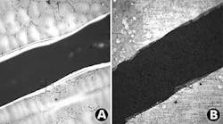
The measured resulting hole quality of the GE pulselettes is shown comparatively qualitatively in Figures 3a and 3b. The respective recast microcracking between a conventional laser pulse and the GE pulselettes can be statistically shown. The magnitude of the microcracking is similar, but the variation is reduced by the pulselettes. Similar results were found for the following: entrance/exit globs, oxide layer, recast, parent metal cracking and maximum recast. The plots represent the results of more than 50 holes analyzed.
From the above results, it can be shown that the pulselette-drilled holes were superior in reducing variation of these results and in most cases reduced the magnitude of the resulting laser damage to the hole/component. On a qualitative basis, it could be argued that the pulselette-drilled holes were "cleaner" than the conventional pulse parameters.
Airflow variation analysisThe airflow average was significantly higher with the pulselettes, by approximately 40 percent. This is particularly confounding because the pulselette holes pinned 0.002 in. smaller in diameter. The advantages are several: a) the pulselette holes are cleaner and b) the glob and maximum recast do indeed impact flow in a laser drilled hole (much debate has historically surrounded these issues).Figures 4 and 5 depict the airflow capability of conventional and pulselette drilled holes, respectively. In this study, eight plates were drilled with each parameter set. The pulselette hole averages were normalized to the conventional average for comparison purposes.
Comparing the two results, the Cpk is approximately 30 percent improved over conventional pulse parameters, as is the standard deviation. This will be further validated in long-term testing. Also, the long-term predicted defect rate (parts out of range) has been reduced by a factor of 10. Thus, the pulselettes, given our current operational limits and requirements, can improve our airflow variation and enable the elimination of inserts.
The resultsThe conclusion reached by the GE team was that the pulselette holes visually appeared to be more round than conventionally drilled holes. This was verified by looking at light through the drilled plates with pin gages inserted in the holes. The pulselette holes typically had small gaps randomly around the perimeter of the hole. The conventional pulse holes were notably elongated in the plane of the angle to the surface. The overall conclusion is that the pulselettes result in a rounder but tapered hole, the average internal surface is smoother, entrance and exits are more repeatable, and there is less burr and dross.One conclusion, based on the energy measured by the breakthrough sensor, was that the first pulse of the first pulselette, when properly focused onto the target, results in a more uniform initial penetration. Thus a more repeatable sequence of percussion drilling results. This "first drill" and the impact on hole variation has also been the subject of much debate.
The breakthrough sensor response, amplitude over time/pulse duration, was seen to be more repeatable for the pulselettes than conventional long-pulse drilling. We furthermore found that the initial breakthrough signal can be correlated to focus position and thus used as a control to account for loading errors.
Next stepsUsing the pulselettes, GE has begun to introduce the process onto the shop floor to improve airflow variation on critical parts. We will shortly begin eliminating wax and inserts on the parts to save labor and time on waxing, dewaxing, disposal and cleaning of the airfoils. This alone will result in more than $0.5 million per year in expenses of inserts and disposing thereof. We are not, however, capable of reaching the ±2.5 percent flow variation long-term goal without additional technology.The results herein demonstrate that the newer commercial laser technologies have tremendous potential for improving industrial laser drilling in critical applications. Similarly, the new solid-state/diode-pumped and alternate wavelength technologies offer similar or even more potential.
GE has experimented with diode-pumped lasers in a Defense Advanced Research Projects Agency (DARPA) program led by TRW. Although the drilled hole quality has been shown to be superior, we have not been able to percussion drill the relatively large (0.015 in. to 0.030 in.) diameter holes incorporated in our current engine designs. We believe this to be a direct result of the much improved beam quality that comes with the diode-pumped efficiencies. We hope to investigate these tools further in 2002.
We have begun the investigation of integrating the calibrated airflow measurement with the laser drilling process. The concept is that once the insert/wax has been eliminated from turbine airfoils using pulselettes, then one can pump controlled air through the airfoil and measure the leakage as each hole is drilled. A statistical average over five or ten holes would then be used to make minor corrections in focus, power/energy, spot size and/or beam quality on the P50 laser. One preliminary result is that the laser exit side burr is virtually eliminated by the air flowing out of the hole and will be investigated further. GE is performing this work and hopes to present the results later in the year. The goal will be to deliver the ± 2.5 percent airflow variation while adding less than 10 percent cost to the equipment.
Todd J. Rockstroh, Doug Scheidt and Clarence Ash are all with GE Aircraft Engines, Evendale, OH. Contact Dr. Rockstroh by e-mail at [email protected].


