Shipbuilding experiences a revolution

Jos. L. Meyer GmbH (Papenburg, Germany) is revolutionizing shipbuilding using laser technology to improve quality, speed and efficiency, because the only way this manufacturer of the largest cruise ships in the world can hold its place against stiff competition from the Far East is by leading-edge technology. Laser systems from Schuler Held Lasertechnik (Heusenstamm, Germany) now play a role in increasing Meyer's technological lead and keeping European shipbuilding on course.
These cruise ships are the floating cities of the high seas with up to 4000 inhabitants at one time. On these ships the journey is the destination and the trip is nothing more than being underway. Worldwide, between 1998 and 2001, two-dozen ships were built, and currently more than 61 of the giant cruise ships are on order. Today, Meyer faces international competition rougher than the storms encountered by its ships on the high seas.
null
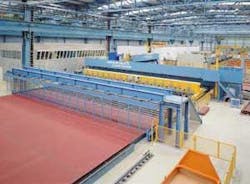
The company's decision in 1999 to build a second construction dock, and thereby double its capacity to two ships per year, was due, in part, to its pioneering spirit, optimism and technological know-how. The company's engineers and technicians also had in mind nothing less than a revolution in shipbuilding methodology. The result is a construction bay for the prefabrication of ship sections that has no equal in terms of its complexity and the degree of automation, with laser technology playing a leading role in this revolution.
Meyer Shipyards, located on the Ems River in North Germany, has been exploring the frontiers of laser technology for a number of years and collecting valuable experience. Now it has developed a completely new laser welding methodology that reduces the construction time in dry dock by 40 percent. This was a project that would come to represent a milestone in the construction of laser systems. The cooperation between Meyer Shipyards and Schuler Held Lasertechnik also produced the largest and most complex laser welding system in the world to date.
The process
Just as in the automobile industry, shipbuilders also try to reduce material consumption and weight in order to keep operating costs as low as possible. In shipbuilding they also make use of the technique known as "tailor-welded blanks," that is, joining panels made of plates of varying thickness as required by the specifications and static calculations of the ship's hull. Panel dimensions, in this case, can reach 20 × 20 meters.
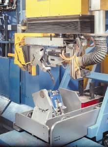
Meyer uses a laser-hybrid process that the company itself perfected. With the aid of MIG welding, filler metal and the seam edge are fusion-welded while the focused spot of the laser (following directly behind) ensures fusion into the root of the seam by means of deep-penetration welding effect. In this way the laser produces a weld that is as good as a conventional root penetration seam even though it is processing from just one side and with a very low angle of beam spread.
Stiffening elements required to reinforce the deck are then fillet-welded onto the panels using the same welding procedure and, again, only from one side. In the process the profiles are welded over the entire thickness of the cross section.
The advantages
Meyer has experienced significant benefits from this new installation. The panels no longer have to be machined for a root penetration weld, a process that becomes more and more difficult as the prefabricated blocks and panels get bigger. Welding rates are much higher than pure MIG welding - but also higher than pure laser welding. Because of the deep penetration, the side angle can be reduced to six degrees, which helps to make dramatic reductions in the quantity of extra wire needed, compared with conventional welding processes. Reducing the side angle also makes for reductions in the cutting volume when preparing the weld.
Narrowing the area affected by heat also reduces the energy input applied per unit length, resulting in tangible reductions in panel distortion. This ensures that the welding process can be automated. Moreover, costly and time-intensive reworking is reduced and the assembly of the blocks in the dock simplified. By using a MIG welding source to apply energy in areas near the surface, the laser is available solely for deep penetration welding, for example, for the process urgently dependent on the laser's qualities. Energy costs are almost halved, compared with pure laser welding.
The equipment
At the heart of the system are four welding machines from Schuler Held Lasertechnik, two butt-joint welding machines for the production of panels and two fillet-joint welding machines with appropriate automation for placement of the reinforcing elements. While the butt-joint welding machines join individual plates to form the deck panels, the fillet-joint welding machines equip the panels with reinforcing elements that extend around the ship in a longitudinal direction. Here, for the first time anywhere, butt-welded seams and fillet-welded seams are applied continuously over a length of 20 meters.
null
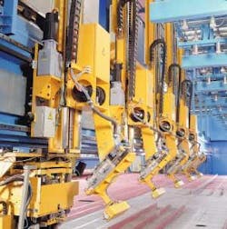
The massive fillet-joint welding machine with its length of 29 meters and a total weight of about 160 metric tons is by far the most ambitious laser system that Schuler Held Lasertechnik has ever built. It also represents a milestone in laser welding technology, because it is the first to supply an entire deck panel with reinforcing elements of various shapes, sizes and kinds in a fully automated mode with no manual preparation.
The data loading takes place as a closed processing chain from the CAD program to the machine. The geometry of the deck is transformed into an EDP operating plan, the working sequences along with the appropriate geometrical information are transferred to the lead calculating unit of the machines. There a specifically produced postprocessor creates the CNC programs from the program instruction.
null
The machine contains 27 CNC axes and three hydraulic axes that are controlled by two CNC units. One of the CNC units controls the five handling functions that serve to place and position the reinforcing elements on the panel. The special challenge for control technology here is that these handling units must be perfectly synchronized in order to work together to process reinforcing elements up to 20 meters long and that require all five handling procedures for reliable transport. Because the welding head and the handling devices are operated by different controls, it is only by precise synchronization of the movements of the head and each individual handling unit that collisions can be avoided. The welding carriage consists of a positioning head (for clamping and orienting of the reinforcing elements), the laser carriage and the MIG carriage. Each subsection has its own travel axes in various spatial directions. The travel range of all three sections have to overlap in order to provide the required functionality for the machine.
Tensioning of the reinforcing elements is by a horizontal, hydraulic clamping unit. In the vertical direction, the weld quality depends on how successfully the gap between the items to be joined is closed. So the blank is rolled onto the base of the profile by a traveling hydraulic pressure roller, with the net press capacity adjusted to the preset figure after removal of the blank weight. After the welding carriage has been positioned on the blank, the reinforcing element is fed into the open positioning head.
For lateral positioning, a camera (vertical camera) looks for the placement line parallel to the line of the reinforcing unit and moves the positioning head accordingly. The same camera is then used for longitudinal placement of the welding head, using a marking made on the blank. Longitudinal placement of the profile is carried out by the handling units, which position the profile relative to the welding carriage. Then another camera, adjusted to the first, receives a marking made on the profile in the middle of its picture.
null
The vertical camera follows the placement line on the panel for proper positioning of the reinforcing elements on the panel during the welding process. A coordinate value for the orientation line is a measurement check. This acts as an online control of the carriage for the positioning head and the y-axis of the laser and the MIG. Three sensors are employed for adjustment of the laser and MIG axes in order to position the laser focal point and the MIG torch to an accuracy of ± 0.1 millimeter relative to the reinforcing element and the plate. This is achieved despite the relatively large deviations in the positioning of the reinforcing elements and the relatively large dimensional tolerances of the profiles and the plates. This precision is required to ensure a good weld.
A major influence on the quality of the weld is how accurately the distance between the laser focus and the MIG current head can be maintained relative to the weld seam root and how well the parameters of the laser and the MIG processes are coordinated. These welding parameters are established in a comprehensive series of tests and stored in the machine's control system in the form of a technology database.
The I-weld machines use a light section sensor to trace the weld line and register any horizontal weld deviation or tramping. The axes of the MIG and laser head are subsequently adjusted, in accordance with the sensor signal. Depending on the size of the deviation, the technology parameter records are modified to comply with the programmed functions of this deviation.
A revolution in shipbuilding
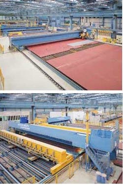
With the help of a laser hybrid process perfected by Meyer Shipyards, four Schuler Held laser systems automatically weld together the ship's panels; first vertically and then horizontally, and then attach the stiffeners of various shapes, sizes and kinds on the wall and floor panels. The major advantages are: 1) the process is fully automated despite the different configurations of the panels, and 2) the size of the system and the quality of the welds permit prefabrication of sections as large as 20 × 20 meters without ever having to turn the panel over.
In shipbuilding, such component size, welding precision and the level of automation amount to a revolution-especially for processes that typically have been done manually. The coordination of mechanics, control and software results in a "mechatronic" system that, in its complexity, represents completely new territory for Schuler Held.
This article was adapted with permission from one that appeared in the 1/2002 issue of Inform, the Schuler corporate magazine. ILS appreciates the cooperation of Schuler in preparing this article.
Meyer shipyard
The Meyer Shipyard in Papenburg can look back on a tradition of more than 200 years in shipbuilding. Family ownership has been maintained over six generations. Meyer is among the most advanced of the world's shipbuilding facilities. The core elements of the shipyard are two huge construction bays under roof, designed for ships up to 150,000 gross tons. In addition to the nearly 2,500 employees of the Meyer Shipyard itself there are an equal number of workers employed locally by suppliers to Meyer, such as companies that build and install interior furnishings and fixtures.

null