Laser processing of glass
Glass presents some tough challenges when using lasers for material processing because of its brittle nature and poor heat transfer. Localized residual heat from the laser beam can cause cracking and chipping, especially on the exit side. Also, the transmissive nature of glass in the visible region of the spectrum limits the number of available laser wavelengths that can be used.
Historically, laser processing of glass has been very difficult due to its inherent physical properties, so there are several challenges that have to be addressed when using lasers for glass processing. The first is choice of laser wavelength. Most glasses transmit in the visible portion of the spectrum, and many transmit over very wide portions of the spectrum outside of the visible. This is usually a disadvantage as it limits the choice of available laser wavelengths for processing, but actually in some applications the transmissive properties can be used to advantage, such as in 'backside processing' where the beam goes through bulk substrate and is used to machine material on the far side. In most cases, the choice of laser wavelength is limited to the infrared (IR) and/or Ultraviolet (UV). As a general statement, the further in either direction from the visible, the better the material absorbs the photons.
Much bigger challenges are faced when considering the brittle nature of the material and the poor thermal conductivity. This is especially true when using the IR lasers, as the first order material interaction is via a thermal mechanism and, therefore, cracks form. Sometimes this can be limited to microcracks during processing, but faults such as these affect long-term reliability of many devices as the fractures propagate over time, causing catastrophic defects. Another problem is the difficulty of getting clean exit holes as bottom side 'chip out' almost always occurs. Finally, many times there is a thermally induced 'glaze' around holes or cuts where the local structure of the material has been permanently changed from the laser process.
Hole drilling
When hole drilling with lasers, it is always necessary to take into account the inherent taper of the laser process, which limits the thickness of material that can be processed with respect to the diameter of the holes being drilled. For glasses, this process has even more limitations as the deeper the hole is drilled, the less likely that heat can escape, thereby causing problems with glazing and especially microcracking. In addition, the exit usually is a problem as the glass shows breakout induced from the thermal stresses and the acoustic shock of the material being ejected through the entrance side as it is drilled.
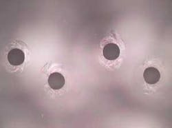
Figure 1 shows approximately 100-µm-diameter exit holes in borosilicate glass drilled with an excimer laser. There are several ways to minimize these effects. First, it is possible to slow the drilling process by reducing the energy and/or repetition rate when nearing the end point so that the minimum fluence is used for final material removal. The second method is to use a sacrificial layer on the bottom to induce artificial mechanical rigidity into the part. Perhaps, the best method is to use a material slightly thicker than needed and do a light lap of the exit (and entrance side if desired). Because of the hole taper, the exit before lapping must be slightly smaller than the desired exit after lapping as the hole diameter gets somewhat bigger as material is removed from the bottom up. The disadvantages to this approach are that secondary steps are needed after laser processing (lapping and probably post lap cleaning) and also one must be very careful not to clog the holes back up during the lapping process.
Etching
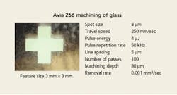
Surface machining of glass suffers from the same drawbacks as hole drilling primarily due to the thermal nature of the process and the problem of crack propagation during and after the process. Recent advances in pulsed laser technology in both the UV and IR have opened up new processing windows. Diode-pumped UV lasers operating at the shorter wavelength of 266 nm (frequency quadrupled) have much more photon energy than even the 355 nm frequency-tripled lasers and the absorption of the material is usually superior. Figure 2 shows a large surface feature etched in glass using the 266 nm laser. Shortening the pulse length of 9.3-micron CO2 lasers by Q-switching has also allowed interesting new applications to be investigated as the heat dispersed in the material is much less than for traditional CO2 lasers. These lasers work well on many types of glass (borosilicate, soda lime), but still the type of glass and depth of machining are important parameters to consider.
There is another method for etching glass that achieves excellent results. It involves using an HF atmosphere to etch with a laser assist. Traditional HF etching uses a mask in intimate contact with the glass surface, which limits etch resolution and achievable depth, and the process is very slow. By using a CO2 laser instead of a mask, very fine features can be generated without using a mask. The surface of the glass is covered in the HF atmosphere and the entire surface is etched to some degree, but at the points where the laser beam hits, the etch rate is on the order of 1000 times faster than on the rest of the areas. This process is somewhat complicated and uses toxic gases, but can give excellent results and can be used for high value added or difficult etching jobs.
Marking in bulk (sub-surface)
Bulk marking is an application of interest to the decorative, medical packaging and other industries where identification information is critical and must be protected from counterfeiting. For decorative applications, IR or 1.06-micron wavelengths are most suitable because glass is transparent at these wavelengths unless the intensity is very high. The process of generating the internal mark is that of thermal fracture resulting in microcracks that are generally 50 to 100 microns in diameter and do not significantly affect the structural integrity of the material so long as they are sufficiently below the surface (>2 mm). For higher quality or shallower marking applications, pulsed UV (355 nm) is more appropriate as the process is inherently less exothermic resulting in smaller microcracks (<25 µm).
Cutting
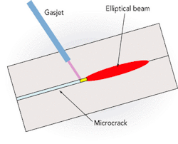
CO2 lasers are being used for glass cutting in the display industry. This is done by using a shaped CO2 beam to generate localized thermal stress buildup, followed by a water/fluid spray that quenches the affected zone creating a controlled crack (see Figure 3). By carefully controlling the temperature profile of the glass, this process can be used to create a clean fracture along any straight dimension of the glass. The advantage is there is no material loss or particles generated during the process and the quality of the cut is excellent. The disadvantage is this process works best for straight line cuts, not contour cuts. Power levels of 100 to 200 W are sufficient for the process and cutting speeds approaching 1 m/sec are possible.
One subset of cutting is cleaving, where the ends of glass fibers need to be cut perpendicular to the longitudinal axis with very straight walls. While it is difficult to cut the fiber directly with lasers, they can be used to nick one edge that provides a fault along which the fiber can then be cleanly broken. In some cases the end of the fiber needs to be shaped with a round surface, and lasers can also be used to slightly melt the end, forming a micro-lens. It is very difficult to precisely control the roundness of this process to high tolerances, but the basic concept is sound.
Waveguide writing
Writing three-dimensional waveguides inside of glass materials (high silica, borate, soda-lime silicate) is of interest to the telecommunications industry. In principle, this application is bulk machining in glass except that the process involves locally changing the refractive index of the material by densification, which means that the process must be non-thermal. Ultrafast lasers with pulse lengths in the femtosecond range provide ideal tools for this process.
Patterning of thin films on glass substrates
While not strictly 'glass machining' per se, this application area is of great interest for a variety of industries such as patterning solar panels, medical imaging detectors and automotive windshields. The basic process involves removing thin metallic, dielectric, optical or organic coatings on glass. Depending on the coating and the laser used, the process can either be done with the laser hitting from the coated side or through the glass from the backside. In order to do backside processing, the laser wavelength must be transparent to the glass. Backside processing has the virtue that the debris generated from the process can be forced away from the glass, minimizing contamination from debris. It is surprising how much debris can be generated in a volume production environment.
Conclusion
Lasers provide a very effective way to machine glass, despite the problems associated with poor thermal conductivity and brittleness of the material. New laser sources such as 266-nm quadrupled Nd:YAG lasers, short-pulse Q-switched CO2 lasers and ultrafast lasers are opening new application areas for the direct laser processing of glass.
Acknowledgement
The authors would like to thank Sri Venkat from Coherent for his valuable input and for some of the figures.
About the Author

Ron Schaeffer
Ron Schaeffer, Ph.D., is a blogger and contributing editor, and a member of the Laser Focus World Editorial Advisory Board. He is an industry expert in the field of laser micromachining and was formerly Chief Executive Officer of PhotoMachining, Inc. He has been involved in laser manufacturing and materials processing for over 25 years, working in and starting small companies. He is an advisor and past member of the Board of Directors of the Laser Institute of America. He has a Ph.D. in Physical Chemistry from Lehigh University and did graduate work at the University of Paris. His book, Fundamentals of Laser Micromachining, is available from CRC Press.
Gabor Kardos
Gabor Kardos is contract manufacturing manager at PhotoMachining (Pelham, NH).
Oleg Derkach
Oleg Derkach is applications specialist at PhotoMachining (Pelham, NH).