Laser stir welding continues to advance
Process can weld several joint configuration types
RICHARD MARTUKANITZ and ISRAEL STOL
Laser stir welding is increasingly being utilized to improve weld quality, properties, and reliability for a wide range of industries, and improvements in laser beam quality and delivery capabilities are helping to spur this growth. The process has wide application in the automotive, aerospace, and fabrication industries, to name a few.
The term "laser stir welding" was coined to describe a process in which the laser keyhole or vapor cavity was manipulated or oscillated at a relatively high rate to cause a stirring action within a larger pool [1, 2]. It has also been referred to as laser beam welding with wobbling. The phenomena is centered upon proper selection of the energy density of the laser and relative rate and motion of beam oscillation based on the thermal properties of the material being processed.
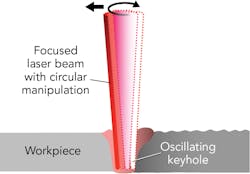
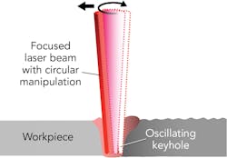
FIGURE 1. Schematic of the laser stir welding process using circular beam manipulation.
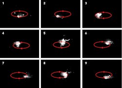
The ultimate effect when the correct parameters are chosen is the integration of energy distributed over the beam oscillation area, allowing the keyhole to cause a hydrodynamic stirring action at the rapidly moving beam. The total energy integrated over the oscillation region is responsible for maintaining the large molten pool, while the local intensity of the beam sustains the vapor cavity during oscillation and stirring within the molten pool [3]. The rapid motion of the oscillated beam establishes a self-healing nature of the keyhole [4, 5]. FIGURE 1 illustrates the laser stir welding process, and FIGURE 2 shows selected images from high-speed cinematography of the laser keyhole or vapor cavity during circular manipulation within the weld pool, all of which were obtained at 5000 frames/s.
FIGURE 2. Selected images of the vapor cavity and the molten pool during laser stir welding with circular beam manipulation (red line shows clockwise motion and direction of the beam while the substrate is moving to the right relative to beam manipulation).
Research conducted during the development of the process had shown that laser beam welds produced on aluminum alloys using the laser stir welding process displayed less weld defects when compared to traditional laser beam welding, along with concomitant benefits of increased size of the weld to accommodate gaps and improve shear strength of lap joints, and enhanced ability to feed filler material. It was also established that by proper selection of parameters that govern the input and distribution of energy in relation to the thermal diffusivity and fluidity of the base metal, the process is easily applied to other alloy systems.
Recent research and applications of laser stir welding have increased significantly since its inception, based on the underlying principle that rapid oscillation of the vapor cavity within the molten pool provides a hydrodynamic stirring action that may reduce defects related to gas absorption and keyhole instability, while also providing simultaneous benefits associated with the formation of a larger weld pool [4-12].
The principle of the laser stir welding process remains the same, but laser sources providing improved beam quality and galvanometer-based systems for beam manipulation enable the process to be effectively adopted and utilized for a broad range of industrial applications.
Laser stir welding process details
Laser stir welding utilizes some form of beam manipulation to oscillate the keyhole or vapor cavity within a larger molten pool. It requires a relatively high rate of manipulation, which may be represented by circular, elliptical, or linear motion, or some other pattern. The manipulation of the beam, and its corresponding oscillation of the vapor cavity within the molten pool, is utilized in conjunction with motion used for the welding path.
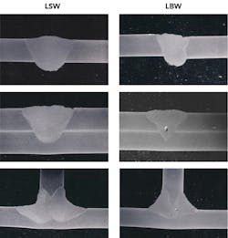
FIGURE 3 shows macrographs of welds on 3mm-thick aluminum alloy 6013-T4 produced using traditional laser beam welding (LBW) and laser stir welding (LSW) for three joint configurations [3]. In the case of LSW, a 3mm circular manipulation of the beam was conducted at 2500rpm during welding—in all instances, filler alloy 4047 was used to suppress solidification cracking during welding. Also, the welds produced using the LSW process were produced at welding velocities slightly lower than the traditional LBW process.
FIGURE 3. Cross-sections of butt, lap, and fillet welds on 3mm aluminum alloy produced using traditional laser beam welding (LBW) and laser stir welding (LSW).
As shown in FIGURE 3, the welds produced using the LSW process exhibit no porosity, while pores are evident in the lap and fillet joint configurations of the laser beam welds made conventionally. This is notable because the metallographic specimens were obtained randomly from the completed welds. However, the reduction in defects caused by gas porosity or pores because of instability and collapse of the keyhole using LSW has also been quantified under more rigorous evaluations.
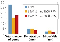
FIGURE 4. Characteristics of butt welds produced on aluminum alloy 6013-T6 using the LSW and LBW processes.
FIGURE 4 shows the characteristics of butt welds produced on 3mm-thick aluminum alloy 6013-T6 using the LSW and LBW processes. All welds were produced using a Nd:YAG laser at 4.5kW with welding velocities between 1 and 2.0m/min. All welds produced using the LSW process utilized a circular beam manipulation that was approximately 3.0mm in diameter at 2500rpm. Porosity associated with these welds were measured by radiographic techniques, and optical metallography was used to determine weld width and depth of penetration. Welds produced using the optimal LSW process displayed a significant reduction in porosity, virtually no reduction in penetration, and an appreciable increase in weld width.
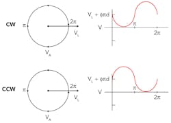
FIGURE 5. Relative velocity (VL) of the beam with respect to the workpiece during LSW with clockwise (CW) and counter-clockwise (CCW) circular beam manipulation.
One aspect of the LSW process that must be considered when utilizing circular or elliptical beam manipulation patterns is the relative velocity of the laser beam with respect to the workpiece. FIGURE 5 shows the relative velocity (VL) of the laser beam with respect to the workpiece for clockwise and counter-clockwise circular beam manipulation. In this case, the rotational welding velocity was set equal to the rotational velocity of the beam.
Depending upon the direction of beam manipulation, the edge of the weld zone where rotational speed is opposing the welding velocity results in a low relative velocity. This condition will result in an increase in energy that can lead to slight undercutting of the weld at this location. (This is illustrated in the right edge of the butt weld produced using LSW in FIGURE 3.) A benefit of linear manipulation, such as through a "dithering" action transverse to the welding direction, is that the overall velocity of the beam relative to the substrate is symmetric to the weld line and does not produce this effect.
As discussed previously, the LSW process can be used to reduce defects during laser welding while also providing other important advantages over the traditional LBW process. These complementary characteristics of LSW include the ability to accommodate significantly wider gaps when welding butt joints, wider interfacial weld widths at the faying surfaces of lap penetration joints that result in increased shear strengths and fatigue life under cyclic loading, capability to weld lap-fillet joints without precise placement of the laser beam and filler wire relative to the joint as required with the traditional LBW process, and ease of introducing sufficient filler material to the welding pool. This last benefit is because of the larger weld interaction area and molten pool created during LSW. In applications that require filler metal additions, this aspect of the process may have significant ramifications for laser welding in high production environments.
Enabling technologies
Recent advances in systems technology for laser welding are having a large impact on the ability to apply LSW in production, which includes new laser technology and digitally driven scanning systems. With the advent of ytterbium-doped fiber and Nd:YAG disk lasers capable of providing good beam quality—that is, laser having a relatively low beam parameter product (BPP)—small spot sizes and high energy densities for keyhole welding may be achieved at relatively long focal lengths. This enables the use of various optical devices, notably scanning systems, to project and manipulate a high energy density beam at reasonably long work distances.
By simply controlling the laser, scanner, and robotic system, LSW can be easily implemented in a fully automated production system where the laser beam may be remotely and precisely projected and manipulated to achieve improvements not readily available through traditional LBW.
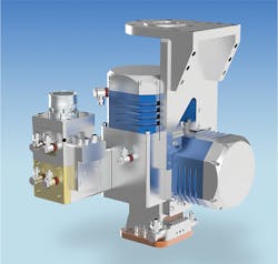
FIGURE 6. A commercial scanning system for high-power beam manipulation for laser stir welding. (Courtesy: Laser Mechanisms)
FIGURE 6 shows a commercial laser scanning system that utilizes water-cooled mirrors for accommodating laser power up to 20kW and is capable of high-speed beam manipulation for LSW. These types of scanning systems may be programmed and precisely controlled to produce various manipulation patterns, and may be directly coupled to fiber-delivered lasers and integrated into mechanized or robotic systems.
Industrial applications
Although originally developed for laser welding of aluminum alloys, LSW has gained considerable attention over the past 10 years. Because of the availability of enabling technologies—namely high-power lasers having high beam quality and digital scanning systems—the process is being utilized in a variety of industries. Applications that require high weld quality, such as in the automotive, aerospace, and medical device industries, can rely on the manipulation or oscillation of the keyhole to reduce entrapped gas porosity, minimize voids cause by collapse of the keyhole, and increase weld width for accommodating gaps and joint mismatch.
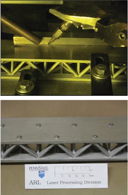
Through correct process parameter selection, LSW may be applied to various alloy systems to produce butt, fillet, lap, and discontinuous spot welds. FIGURE 7 shows the use of LSW using circular beam manipulation for producing spot welds on an aluminum sheet and a cast aluminum lattice structure. In this case, filler material was also added to suppress solidification cracking of the aluminum alloys being welded.
FIGURE 7. Images of laser stir welding for producing spot welds on a stiffened aluminum structure. (Courtesy: The Applied Research Laboratory, Pennsylvania State University)
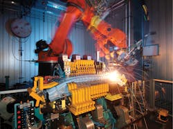
Because of the need for high productivity and weld quality, the automotive industry has readily adopted LSW, which includes applications for seaming, sealing, and welding of body structures, as well as welding of transmission components. In many instances, the process has been implemented in automated systems that control the laser, scanning system, and robot. Such a system has been developed by Daimler AG and was awarded the prestigious Innovation Award for Laser Technology (FIGURE 8). The system is named RobScan, and Daimler claims that it has resulted in increased productivity over spot welding, while having the ability to bridge gaps and mitigate weld craters during weld termination [13].
FIGURE 8. The RobScan system developed by Daimler AG for automotive applications.
The advantageous features of the LSW process have been demonstrated for welding numerous joint configurations (square-butt, continuous, and discontinuous spot and intermittent seams, as well as lap-penetration, lap-fillet, and fillet joints) in various alloy systems (aluminum, ferrous, copper, and magnesium alloys) ranging in thickness between 0.5 to 4.5mm.
In addition to demonstrating these benefits, LSW has shown near-universal applicability for production welding of structures and components for a broad market segment, which includes naval and marine (decks and integrally stiffened panels), automotive (load-carrying and non-load-carrying portions of vehicles, such as1 internal and external panels, chassis, doors, and pillars), transportation (truck beds, walls, and cabins), and aerospace (stiffened panels, bulkheads, and decks).
The last five years has seen a rapid acceleration in the adoption and use of LSW within the United States and abroad, and this trend is expected to continue.
REFERENCES
1. I. Stol and R. P. Martukanitz, "Laser welding with beam oscillation," U.S. Patent 6,740,845 B2 (May 25, 2004).
2. I. Stol and R. P. Martukanitz, "Laser welding with beam oscillation," EU Patent EP 1 534 460 (2004).
3. R. P. Martukanitz, I. Stol, J. F. Tressler, and C. J. Warren, "Development of the laser stir welding process for aluminum laser beam welding," Proc. ICALEO, 712-718 (2005).
4. R. P. Martukanitz, "A critical review of laser beam welding," Proc. SPIE, 5706 (2005); doi:10.1117/12.601655.
5. H. Haferkamp, O. Berend, O. Meier, and L. Engelbrecht, "High-frequency beam oscillation to increase the process stability during laser welding with high melt pool dynamics," Proc. ICALEO, 1032-1041 (2005).
6. R. Martukanitz and J. Tressler, "Mixing it up," Industrial Laser Solutions (Mar. 2006); see https://goo.gl/8Z4e5V.
7. A. Mahrle and E. Beyer, "Modeling and simulation of the energy deposition in laser beam welding with oscillatory beam deflection," Proc. ICALEO, 714-723 (2007).
8. F. Schmitt et al., J. Laser Micro Nanoen., 5, 3 (2010); doi:10.2961/jlmn.2010.03.0003.
9. T. Hammer, Dance of the Photons, Laser Community, Trumpf GmbH (Feb. 2011); see https://goo.gl/GaWbko.
10. M. Kraetzsch et al., Phys. Procedia, 12, 142-149 (2011).
11. T. Tsukamoto, H. Kawanaka, and Y. Maeda, "Laser narrow gap welding of thick carbon steels using high brightness laser with beam oscillation," Proc. ICALEO, 141-146 (2011).
12. C. Thiel, A. Hess, R. Weber, and T. Graf, "Stabilization of laser welding processes by means of beam oscillation," Proc. SPIE, 8433, 84330 (2012).
13. "RobScan laser beam welder wins award," Industrial Laser Solutions, 23, 6 (2008); see https://goo.gl/4Dt1P2.
Dr. RICHARD MARTUKANITZ ([email protected]) is director of the Center for Materials Processing through Direct Digital Deposition (CIMP-3D) at Pennsylvania State University, University Park, PA, www.cimp-3d.org, and ISRAEL STOL is an engineering consultant specializing in welding and manufacturing technology.
