Design with lasers in mind
Charles Caristan, Gulam Mohiuddin, Mariana Forrest, and Nasim Uddin
Product design guidelines for manufacturing with industrial lasers can yield maximum product value
To mitigate the pressure on relocation induced by the globalization of the economy, manufacturing enterprises are forced to seek and adopt solutions to become more competitive and agile and ultimately to enjoy healthy, profitable growth at the local level. Industrial lasers have already had an overall beneficial impact on manufacturing’s survival and growth. Here, we outline a strategy to generate additional solutions for the automotive industry by developing specific product design guidelines for manufacturing with industrial lasers while yielding maximum product value. These design guidelines intend also to help bring products to market faster by improving the first-time product quality and significantly reducing the rework in design.
Challenges and opportunities
Decisions made during the product/part design period determine 70 percent of the product’s cost and quality. Reaching and engaging the product design engineers (from which everything starts) can accelerate the time to market for new technologies. More products will be designed such that benefits of manufacturing with lasers will be enhanced for an optimum product value. To that end, a clear documentation of requirements and tolerances for components and assembly laser manufacturing and support resources is needed and should be made accessible to these design engineers.
Many “low-hanging-fruit” technologies are available for applications opportunities including laser marking, cutting, welding, drilling, and cladding. The degree of difficulty for successful implementation varies, with marking and cutting being the applications that benefit the most from standard off-the-shelf systems. Welding applications are also heading towards easier implementation with the standardization of packages composed of articulated robots and lasers. Clearly the value perceived by the car manufacturers for each application must remain the main criteria for selection of an application that will impact product design accordingly.
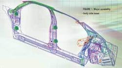
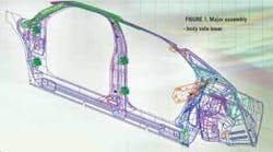
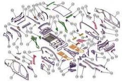
As a real-life example, welding solutions for the engineering product design of a major assembly body side inner (see Figure 1) must meet the following criteria/requirements:
- Architectural requirements are a ‘given’ from styling ‘Executives’ - there is no room to negotiate, although they do follow certain fabrication guidelines.
- Structural and safety requirements are now dramatically changing and putting high demands on Body-In-White (BIW) to meet them-an example is the Federal and IIHS crashworthiness requirement.
- Customer and competitive demands are both driving the BIW to smaller gaps and almost perfect flush for appearance.
- All of the other product design requirements will affect how we manufacture the BIW.
With existing manufacturing processes we can only add cost and mass to meet new requirements. However, laser welding can improve this situation by enhancing design flexibility, for example by enabling single-side welding of two or even three metal thickness joints (see Figure 2). Complete design guidelines for material, shape and geometries, thickness, flanges, and coatings are being developed to take advantage of the new design flexibility and opportunities when laser welding and laser cutting are incorporated in the control plan for this product.
Reduced time-to-market
The speed of implementing new laser based technologies varies from one industry to another. The fastest adopter of new technologies is the electronic and telecom industry where time to market can be as low as two years, enabling the introduction of new products as fast as every six months. Interestingly, the first industrial laser cutting machines for metal fabrication went into the electronic and telecom industry in the mid-1970s as a means to replace less-flexible turret-punch presses. To this day, this market remains the largest user of industrial lasers for metal fabrication.
Conversely, the shipyard, railroad, and automotive industries are much slower adopters of new processing technologies; these industries put more emphasis and resources in development and adoption of new materials. Consider this: the first welded tailored blanks were innovated in the 1960s by the Budd Company in Philadelphia using a mash seam welding technique to assemble dissimilar blank thickness to make a body side aperture tailored blank. In the 1970s A.O. Smith tested a beta site production using electron-beam welding. In the 1980s Toyota in Japan and Thyssen in Germany started laser welding tailored blanks in high-volume production beta sites. It was not until 1993 that mass adoption by almost all car manufacturers worldwide began. This indicates an unbearably mediocre 30-year span before market adoption of a true innovation such as tailored blank products. It turns out that for this mass adoption, laser welding became the overwhelming method of choice to join these tailored blanks.
Cut-to-shape laser blanking
While advances in tooling and materials have reached high levels of technological and scientific sophistication, in some areas of automotive manufacturing production methods developments have taken the back seat. For example, although steel alloys have been the subject of tremendous technology development and advances leading to the increasingly popular use of advanced high-strength-steel materials, sheet metal blanking in production is still processed with the same method today as it was during the pioneering days of Henry Ford and Frederick Taylor, that is, with presses and blanking dies to basically “bang steel.”
In a rare example of process change success, automotive sheet metal cutting for prototype development parts is almost exclusively produced by laser cutting to take advantage of its flexibility and low tooling costs as compared to press die-blanking. However, mechanical shear and press die-blanking still reign as the absolute methods of choice for volume production of sheet metal blanks. Today’s high-speed blankers can cut blanks at rates of 60 punches per minute and more. When equipped with rolling bolsters to ease and speed-up die changeover, set-up change can be achieved in less than 30 minutes. For current JIT batch volume productions on the order of 1000 blanks per batch, such blanking press lines operation could be described as spending 50 percent of operation time in non-value-added moving of tons-heavy blanking dies in and out of a press. As successful and proven as it has been over the past decades, press die-blanking is less adaptable to current productivity, agility, and lean manufacturing requirements than laser blanking.
For cars and trucks consumed in North America, the number of models offered went from 1125 in 2000 to 1600 in 2005, despite the total number of vehicles sold annually remaining flat around 17 million and the number of vehicles manufactured in the USA also staying flat at about 12 million throughout all these years.
The multiplicity of models trickles down to an increase in the number of blanking dies required. Each vehicle body platform comprises more than 200 blanks that need to be cut ultimately from coils (see Figure 3).
Of these, about 50 percent are rectangles or trapezoids sheared on cut-to-length lines. The other half has configured geometries and requires production with presses and blanking dies. Although many models share common underbody platforms, the total number of blanking dies reaches astronomic scale. With blanking dies initially costing from $25,000 to $250,000, depending on complexity and cutting performance, it is also estimated that, on average, maintenance, storage, transportation, and repair service charges can increase the total cost over a five-year die lifetime to three times the initial cost. Blanking dies expenses in the North American automotive industry alone are estimated to be $0.5 billion per year with an asset inventory of close to $10 billion. By reducing the total number of dies, high-speed laser blanking could generate tremendous tooling cost savings.
The main enabler for high-speed laser blanking is the development in high-power laser resonators for metal cutting; high rigidity motion systems powered by linear motors; and computer numerical control systems that can process with high motion contour accuracy at high acceleration. Such systems are available off the shelf and can achieve production cutting speed of 30 m/min or more for automotive-grade 1-mm-thick steel.3-5 As many high-speed laser cutting machines as necessary can be integrated within a coil-fed blanking system to enable JIT production batch requirements. Changeover from one part to another can be achieved by the push of a button and with minor de-stackers, end-effectors, and coil change downtimes. The changeover does not require rolling bolsters or die change downtimes.
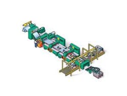
The system concept illustrated in Figure 4 is coil-fed and equipped with two standard high-speed laser cutting systems installed in a “progressive” configuration.
Blank design guidelines
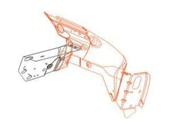
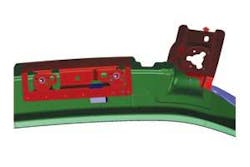
Because high-speed laser blanking does not require expensive dedicated tooling, it leaves almost free range for product design engineers and die engineers to design part contour near net shape manufacturing. Criteria such as production volumes, nesting efficiency, and material utilization are being used to develop the design guidelines for blank contours (see Figures 5 and 6).
The net benefits translate into savings in net piece costs for blanks and easier formability for downstream stamping operation. Further, they contribute to a leaner, more agile, safer, more efficient, and more rapid automotive manufacturing, ultimately leading to increased profitability. The table summarizes the benefits discussed above.
Based on the above, it becomes clear that
- Laser processing is ripe for more mass adoption in industrial manufacturing of automobiles.
- In many cases enabling off-the-shelf turnkey machines and systems already exist and have been demonstrated.
- The potential economic benefits to automotive manufacturing are extraordinary; and taking advantage of them will hinge on the ability to establish the necessary industry-specific design guidelines.
- The ILUC member companies are instrumental in actively pursuing this leading effort. The next step will be the exclusive release of the 2006 executive summary which will highlight the progress to date in establishing content and means of distribution of design guidelines for specific product families, their engineering, manufacturing and business impact, and corresponding comparative scale analysis of laser equipments for the processing of various materials. Charles Caristan is with Air Liquide, Gulam Mohiuddin is with General Motors, Mariana Forrest is with DaimlerChrysler, and Nasim Uddin is with ILUC. Contact Uddin at [email protected] or (734) 944-5850.
References
- Nasim Uddin, (Private Communications) Summary of the first meeting of ILUC Product Design Guidelines for Manufacturing with Industrial Lasers, GM Technical Center, Warren, MI, April 2005.
- Gulam Mohiuddin, Tony Castillo, Nasim Uddin, “Laser Processing: Design Methodology,” ALAC 2004, Ann Arbor, MI, September 2004.
- J C Mombo Caristan, “Laser Blanking: Keeping up with Multi-Model Production Needs,” Forming and Fabricating magazine, SME, Vol. 7 No. 8, August 2000
- J.C. Mombo Caristan, “Laser Blanking vs. Die Blanking”, Detroit, MI , proceedings of the Laser Applications in the Automotive Industry Conference, ICALEO 2000, November 2000
- J.C. Mombo Caristan, W Penn, N Karube, “High Speed High Power Laser Blank Cutting & Welding”, ICALEO 1999, pp. A23-41, San Diego, CA, November 1999
The ILUC initiative
The International Laser Users’ Council (ILUC) is dedicated exclusively to the evaluation, promotion, and management of knowledge related to laser processing, engineering, and applications on a global basis. It was initially formed in the early 1990s to create and sustain a user-driven forum for business growth through the efficient use of laser technology. Its objective is to serve as an independent global authority on laser process integration into product design, engineering, manufacturing, quality, and reliability.
The goal of the Product Design Guidelines for Manufacturing with Industrial Lasers initiative-being carried out by the ILUC1-is to deliver arrays of optimization options at the source, meaning starting with the design of the part or product itself, such as to maximize the product’s value defined as: Product value = [product performance] x [return of investment in equipment and tooling].
ILUC’s headquarters are in Ann Arbor, Michigan, and Dr. M. Nasim Uddin is the president. For details, please contact [email protected] or phone (734) 944-5850.
