Inline vision for laser beam positioning
M.F. Buk and W.C. Choy
A new type of scan lens provides workpiece alignment and improves scan-head accuracy
A growing trend toward miniaturization requires that companies find new ways to manufacture their products. The manufacturing community faces many challenges as the demand for higher accuracy, higher speed, and lower cost increases.
Laser processing is an important method for achieving this goal because the laser beam can be focused to an exceptionally small spot, and it can do pinpoint processing without affecting nearby areas, so it can be used in many materials processing applications such as marking, welding, and cutting. As the laser light is weightless, a common method is to use two mirrors mounted on rotating galvanometers to achieve the x and y movement of the beam to achieve high-speed manufacturing processes. Adding a special focusing lens, called a scan lens, after the mirrors produces a scan-head laser beam positioning system.
Scan-head technology has come a long way, and it now can reach high speed and high accuracy at a reasonable price. Galvanometers can attain precise rotation with good long-term stability. The other major component, the scan lens, is being manufactured with good accuracy. Real-time software compensation can now take care of the nonlinearity of the marking field caused by the scan lens using computers with high processing speed.
However, scan-head technology still has a shortcoming-high (absolute) positioning precision is difficult to obtain due to various factors such as component-installation tolerances, f-Θ lens tolerance, and workpiece-position-holder tolerance. Furthermore, as the workpiece gets smaller, accurate positioning and handling are also a challenge. Techniques including the use of precision jigs and fixtures or vision-based external camera alignment with x-y stage-movement systems have been used. These methods not only consume more space, but they are more complex and increase cycle time and cost and introduce unwanted vibration into the system.
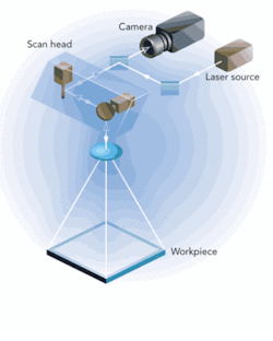
A new type of scan lens with multiple color compensation that allows proper focusing of different wavelengths in the marking plane is now available to do this workpiece alignment and improve scan-head accuracy. This is accomplished by propagating the visible light beam up the same path used by the laser beam going down. The visible light beam enters the camera after reflection by the two pieces of moving mirrors and separation from the laser beam by a beamsplitter mirror.
ScanVision solution
The Hylax ScanVision laser comes from the simple idea of having “vision” through the laser path, through the scan head, where it is heading on its targeted workpiece. The camera is placed in-line with the laser path (see Fig. 1). With this setup, visible light can travel through the same path as the laser beam, and absolute positioning of the galvanometer can be tuned (by software algorithm) to a higher degree of accuracy. Hence, laser positioning compensation by galvanometers up to micron-level accuracy can be realized. As the beam path is the same for both light beams, any deviation or long-term drift of the galvanometers does not affect the accuracy of the system.
Principally, this setup puts the visible and laser light in near-zero tolerance between each other such that all the tolerances of conventional vision-assisted laser systems, namely the x-y table, f-Θ lens, galvanometer-positioning errors, and workpiece and jig tolerance, are eliminated. Also, as vision positioning and laser processing are done without mechanical movement between setups, there are fewer error factors introduced. Other advantages are compactness, simplicity, and reduced processing time.
Other challenges include getting the visible and laser light to be at the same focal plane and to have a clear image throughout the scan field. The big hurdle is the fact that the visible and laser light do not really go through the same path. As they are of different wavelengths, they tend to deflect at slightly different angles when passing through optical components at an angle, for example.
Application methodology
To use this system for workpiece alignment before laser processing, there must be a setup procedure. A golden unit is placed in the scan field, and two points on the unit are chosen as fiducial points. The galvanometers are moved until each of these positions comes into camera view. An image is grabbed and taught each time. The laser processing pattern is then aligned to create the desired result in the correct position on the workpiece. Two points are required to account for x, y, and Θ drift.
Subsequent workpieces can be placed at roughly the same location. Images at the same two positions are grabbed, and using image-processing software the x and y differences can be calculated. Through these values the actual linear and angular drift of the workpiece compared to the golden unit is worked out. The laser-processing pattern is then moved and rotated by the drift amount to compensate for the difference.
Subsequently the galvo mirrors can be moved to different positions to grab images of the post-process result. Image analysis can be done to determine the correctness and quality of the processing. All this is done without movement of the scan head, camera, or workpiece.
Applications
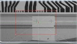
Test circuit connections are built into flat panel displays (FPDs) for certain process requirements and quality tests. At the end of the line, the test circuit lines need to be cut (see Fig. 2). As FPDs get smaller, the patterns shrink, which means the cut accuracy has to be made tighter. Furthermore, the FPD edges may not be accurate enough to be used for alignment. The vertical positioning accuracy requirement of the cut line is ±10 µm, with a laser spot size of 50 ±5 µm.
Previously, this process was done by a fixed optics laser. An x-y stage moves the camera above the two fiducial points, one after another, to derive the exact physical position. The x-y table cutting trajectory is then calculated and the laser cutting commences. Finally, the workpiece is moved to a post-cut inspection station where the camera is again fixed onto an x-y stage and images are captured at different locations to confirm the cut is good.
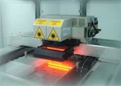
With the ScanVision laser system (see Fig. 3) every x-y movement is taken care of by the galvanometers: two fiducial-point checks, laser cutting, and post-mark inspection are all done in one station, in very short time. This is because the galvo movement is less than 10 ms compared to 100 ms for the fastest x-y stage.
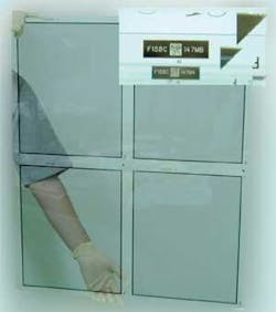
For efficiency, FPDs are manufactured in a big glass-panel form (see Fig. 4). The glass is cut into smaller, usable panels for use in LCD TV, mobile phone display, and PDAs. Material-tracking data markings are needed on specific chrome-coated locations of the FPD. This is done at the beginning of the manufacturing process, on a big piece of uncut TFT glass panel. The data marks are made on every subpanel.
In most cases, marking specs allow a maximum of 15-μm positioning tolerance. With the ScanVision, an x-y gantry transports the dual ScanVision lasers to mark the subpanels section by section. With the built-in, high-accuracy vision compensation, all marks on the subpanels can be done within the required tolerance, without needing a highly precise mechanical positioning system. As the marking uses 2D codes, each mark is captured by the same camera and decoded for a good mark.
The biggest panel-size machine incorporating this technology is a Generation 6 (G6) panel of 1500 × 1850 mm. These panels are transported by a high-speed conveyor system, where the stopping position can deviate in the range of millimeters. However, as long as the fiducial mark is within the camera field of view, this is not a problem. Furthermore, even if it sometimes falls outside, a rapid searching pattern can be done to find the fiducial because the galvo mirrors can move fast. As a fiducial registration is done just before every mark and the time between the two can be less than 100 ms, the chance of the workpiece drifting during that interval is negligible.
The hard-disk-drive industry, facing competition from newer alternative technology, such as flashRAM, has been driven toward miniaturization, increasing capacity, improved robustness, and lower manufacturing cost. This translates to a higher need for manufacturing precision and throughput.
The suspension unit of the head gimbal assembly requires spot welding of high accuracy and speed. Hylax is building a welding machine with a ScanVision laser that will double the throughput of previous models.
Chip package marking
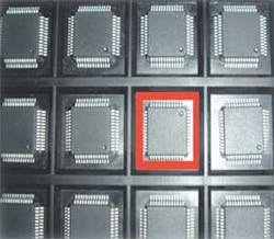
In the back-end IC manufacturing process, ICs might be packed in JEDEC trays, and ICs in the tray can have the wrong orientation due to human error (see Fig. 5). IC users cannot accept wrongly orientated units that are placed automatically without further checks of the PCBs. The potential damage and loss suffered might be astronomical. This is especially true for products such as automotive SRS airbag sensors.
ScanVision laser has helped solved this orientation issue with a marker deployed in the tape and rail machine (final packaging process) that uses vision to determine the correct position and inspect the IC for correct orientation before laser marking on it.
Another customer requires the addition of laser marks to its originally marked IC chips. As the original markings could have been done offsite, each with its own drift, the add-on markings cannot be set at a fixed position or the markings on the same line will look strange. The ScanVision laser marker can do a registration on the original mark and adjust the new markings to keep in line with the old.
Mum Fatt Buk is president and Woon Chao Choy ([email protected]) is the sales and application manager for Hypertronics Pte. Ltd., Singapore (www.hylax.com).
