Lasers in the shipyard
C. Thomy, F. Wagner, F. Vollertsen, and B. Metschkow
Laser joining of aluminum to steel for modern yacht construction
In modern shipbuilding (especially of yachts and military vessels), material combinations of aluminum and steel are used to improve structural properties, predominantly in stiffness, weight, and position of the center of gravity. Because it offers a beneficial influence on the position of the center of gravity of the ship structure, the hull is normally manufactured from steel, while the upper decks or the deckhouse are normally made from aluminum alloys.
Until now, the joint between these two materials has been made by explosion-clad aluminum-steel hybrid profiles (for example, Triclad-www.triclad.com), which can be joined with conventional processes to the aluminum and the steel side of the structure, respectively. For design and cost considerations, however, there is considerable interest in alternative joining concepts for aluminum/steel joints. One concept is the application of aluminum-steel joints for side panels of deck houses in yacht construction, where typical material thicknesses are about 3 mm (see Fig. 1). With such standardized sidewall elements, a transition from the steel deck to the aluminum deckhouse should be possible.
By using laser-based joining processes for aluminum/steel joints, material thicknesses of up to 2 mm (aluminum side) were achieved previously.1,2 Building on this state-of-the-art process, the Bremen Institut für angewandte Strahltechnik (BIAS) has developed, together with laser users, yacht designers, and shipyards, a laser/MIG hybrid joining process for joining of aluminum to steel in butt-joint configurations about 3 mm thick.
Hybrid joining process
In this project on laser beam joining of aluminum-steel joints, a CO2 laser/MIG hybrid joining process was applied (see Fig. 2). In the hybrid process, the laser beam provides high power density, thus allowing keyhole welding and high joining speeds. Consequently, due to a decreased heat input, the formation of intermetallic phases is reduced.3
The MIG torch supplies the gas shielding for the melt pool and the filler wire, which is molten by the MIG arc during processing. Because the power density of the arc is low compared to the laser beam, the MIG process creates a wide melt pool, thus promising good gap bridging and wetting of the steel sheet. Both heat sources, CO2 laser beam and MIG arc, are positioned with an offset to the face side of the sheets onto the aluminum sheet to avoid melting of the steel. Otherwise, large amounts of brittle intermetallic phases would be formed, consequently decreasing the strength of the whole joint. The process is arranged in such a way that the leading laser is followed by the lagging arc.
Aluminum-based filler wire (AlSi12) is applied to increase the melt volume, which increases the wetting on the steel side and decreases the possibility of hot cracks in the weld seam. Another benefit is the alloying of silicon into the weld seam, improving the strength of the joint area and limiting the formation of intermetallic phases.4
Between the face sides of the sheets the gap can be varied between 0 and 1 mm, still obtaining satisfactory results. To support a good wetting of the aluminum melt on the steel, flux is applied on the steel side of the joining zone to break up the oxide layer and to decrease the surface tension of the melt, thus improving the wetting.
Experimental setup and program
The laser/MIG hybrid experiments were performed using a TRUMPF TLF 6000 CO2 laser. A Dalex Vario MIG 400L (W)-B power source (operating in pulsed mode) together with an Abicor Binzel torch were applied for the MIG process. Both heat sources were combined in a hybrid welding head, the arc being positioned 5 mm behind the laser and at an angle of 35° to the laser beam. Shielding gas (mixture of argon and helium) was supplied through the MIG torch. Helium was necessary to prevent the formation of shielding plasma, which may occur if pure argon is used in CO2 laser processes at higher powers. For root protection, argon was supplied.
The joining experiments were carried out on the material combination AA 6056 (3.6 mm) and St 22 (3 mm, no zinc coating). AlSi12 (diameter 1.2 mm) was used as filler wire. Prior to joining, the sheets were cut into strips 50 mm wide and 400 mm long; no further edge preparation took place. The sheets were cleaned with alcohol, and flux was applied to the steel. Parameters varied included gap, joining speed, wire feed rate (and, consequently, arc power), as well as the position of laser spot and arc relative to the edge of the joining partners (offset laser/offset MIG). All specimens were then subjected to metallographic analysis and static mechanical testing.
Results
The molten aluminum wets the steel sheet (which was not molten during processing) on the top and bottom side of the joint (see Fig. 3). While on the upper side a wetting length measuring about 2 mm was achieved, the wetting on the lower side is less: approximately 1.5 mm long. The reason for the severe porosity found in all joints is considered to be in the use of flux. This is backed by the fact that the amount and size of the pores is higher close to the steel sheet and the seam surface. However, without flux, wetting length would be much lower and much less regular, consequently requiring the use of flux notwithstanding the occurrence of porosity.
Along the interface between steel and aluminum an intermetallic phase layer was formed, as shown for the face side in Fig. 3. The thickness of the phase layer of the joints varied between 1 and 3 µm, the highest thickness occurring on the upper side of the weld seam.
Looking at the influence of laser power and wire speed while keeping all other parameters constant, it was observed that the wetting of the steel sheet by the aluminum melt increases with higher wire speed, as well as with higher laser power. In the case of a higher wire speed, the increasing melt volume leads to improved wetting, whereas a higher laser power results in a higher wetting length due to a bigger melt volume caused by the higher heat input.
Moreover, a strong correlation of the intermetallic-phase-layer thickness with the laser power and the offset of the MIG process was established. Comparable to the wetting length increase, laser power causes an increasing thickness of the intermetallic phase seam. This is due to the higher heat input, which leads to higher temperatures and thus to an increased diffusivity of the joining partners. The same phenomenon can be observed for smaller offsets of the MIG-process to the steel sheet. Thus, higher temperatures, in particular on the steel side, are reached, and the formation of intermetallic phases is supported.
Finally, and most relevant to the application, the dependence of the tensile strength of the aluminum/steel joints from joining speed and wire speed was considered. The tensile strength increases with lower joining speed and/or lower wire speed. A decreasing joining speed leads to a deeper penetration of the aluminum and thus to a better wetting of the steel sheet on the lower side of the joints. A higher wire speed provides more aluminum melt, which also results in a better wetting. However, an increased wire speed requires a higher heat input by the MIG process, thus leading to the formation of thicker intermetallic phases, which decrease the joint strength.
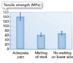
Within the experimental series, tensile strengths of up to 140 MPa were achieved for joints. In the case of inappropriate joint properties, such as melting steel or wetting only on the upper side of the joint, much lower strengths were measured (see Fig. 4). The melting of the steel was caused by a too small laser offset (0.1 mm), whereas the insufficient wetting was due to a too low laser power of 3 kW. The failure of all three test samples occurred on the face side of the joint, along the intermetallic phase layer. In the case of insufficient wetting and melting of steel, the tensile strength is only about 60 MPa.
The results show that for the production of samples with strengths greater than 100 MPa two significant influences have to be considered. Whereas the wetting length of the weld seam on the steel side should be high, the intermetallic phase thickness should be reduced to a minimum. However, both properties cannot be optimized by variation of parameters at the same time. For higher heat input or a lower offset of the heat sources, wetting, as well as phase formation, increase. Accordingly, a decreasing of the intermetallic phases (for example, by lower laser power) simultaneously leads to lower wetting lengths.
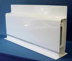
Based on these basic investigations, demonstrator profiles from aluminum and steel (3+3 mm, 1-m seam length) were joined (see Fig. 5). In these trials, the concept from Fig. 1 for sidewall elements in deckhouses was successfully implemented. Thus, the feasibility of joining of aluminum to steel for shipbuilding applications was successfully demonstrated.
Using a laser/MIG hybrid welding process, aluminum-steel joints in butt joint configuration (sheet thickness ~3 mm) were successfully joined. By melting the aluminum side, a wetting of the steel side (which itself is not molten) is obtained. An intermetallic phase layer is formed along the face side of the steel sheet.
Understanding the process
To improve understanding of the process, the influence of process parameters on joint properties was investigated. It was established that wetting length and intermetallic phase layer thickness increase with increasing heat input. Considering the static strength of the joint, it was established that it increases with increasing wetting length and decreases with increasing intermetallic phase layer thickness. Therefore, an optimization of heat input is required to find an optimized compromise between the two conflicting tendencies.
In the framework of the studies reported, a static strength of up to 140 MPa was achieved. This is a significant improvement compared to the so-called Triclad profiles used in shipbuilding today. Building on these results, demonstrator profiles from the deckhouse of a yacht could be produced in an industrial environment. Thus, the potential application of the process and the product were demonstrated successfully. In a next step, the qualification of the process together with the end user and the classification societies is intended.
C. Thomy, ([email protected]), F. Wagner, and F. Vollersten are with Bremen Institut für angewandte Strahltechnik GmbH, Bremen, Germany, and B. Metschkow is with Innovative Fertigungstechnik GmbH, Neu Wiendorf, Germany.
REFERENCES
- M. Kreimeyer et al., “Combined Welding-Brazing Process for Joining Aluminum-Steel Tailored Blanks with High Power Sources,” Proc. 2002 IBEC and ATT Conferences on CD-ROM, ISBN: 0-7680-1066-7.
- H. Bergmann et al., “Untersuchungsergebnisse zum Laserschweißen von Aluminum auf Stahl für Außenhautanwendungen,” European Automotive Laser Application, Bad Nauheim, Automotive Circle International, Berlin (2000).
- C. Radscheit, Laserstrahlfügen von Aluminum mit Stahl. Dissertation Universität Bremen 1996, BIAS Verlag (1997).
- F. Wagner et al., “Phasenbildung beim Laserstrahlfügen von Fe/Al- Verbindungen,” Löt 01, Aachen, DVS-Berichte Band 212, DVS-Verlag, Düsseldorf (2001).
Acknowledgement:
The authors are grateful for the funding of the European Commission within the Craft-project “JODIS” (Contract No. COOP-CT-2004-508091).


