Laser joining carbon fiber-reinforced plastic to stainless steel
Method eliminates environmental drawbacks
SEIJI KATAYAMA and YOUSUKE KAWAHITO
A group at the Joining and Welding Research Institute (JWRI) of Osaka University in Japan, under the direction of Professor Seiji Katayama, has succeeded in direct laser joining of carbon fiber-reinforced plastic (CFRP) to AISI 304 metal. ILS asked Professor Katayama to present details of this study.
Carbon fiber-reinforced plastic (CFRP) is currently attracting great attention due to the material's high strength-to-weight ratio, excellent corrosion resistance, and outstanding fatigue properties, which has led to its use for aircraft, automobiles, and other products. The automobile industry is especially interested in the thermoplastic-type CFRP, where it is expected to shorten production time.
Joining of plastic or CFRP to metal is usually conducted by using adhesive bonds (glues) or mechanical tools such as bolts and rivets. However, these joining processes have several drawbacks, such as environmental restriction of volatile organic compound (VOC) emission, a long bonding time, and an increase in weight due to bolts or rivets. Therefore, laser-assisted metal and plastic (LAMP) direct joining has been developed by Professor S. Katayama's group to rapidly produce strong joints between commercially available metals such as steel, stainless steel, and aluminum alloy, and engineering thermoplastics such as polyamide (PA), polyethylene-terephthalate (PET), and polycarbonate (PC) using a continuous-wave (CW) Nd:YAG laser, diode laser, fiber laser, or disk laser.
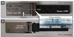
LAMP joining was applied to produce a strong joint between a CFRP sheet and Type 304 stainless steel plate by producing a partially penetrated weld in the metal with a CW disk laser. FIGURE 1 shows the laser lap joint between a polyacrylonitrile (PAN)-type, PA-matrix CFRP sheet with longer carbon fibers of 3mm thickness and 20mm width and a Type 304 stainless steel plate of 3 mm thickness and 30 mm width before and after the tensile shear test. The cross-sectional photo (INSET) demonstrates a laser weld bead made in stainless steel by a shallow keyhole. Moreover, the melted area is widely formed inside the CFRP sheet near the joint interface. It is observed in FIGURE 1B that black CFRP remains adhered to the bottom surface of the Type 304 stainless steel plate. In particular, adhering CFRP is chiefly recognized on the steel plate under the laser weld bead. Part of the steel is also found on the interface surface of CFRP sheet. These facts suggest that the formation of a strong bonded joint is feasible.
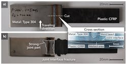
FIGURE 2 shows the tensile shear test results of joints made under different disk laser irradiation conditions. The results show that the maximum tensile shear load (strength) of the joint was about 4800N (for 20mm-wide CFRP) under the proper conditions of 2kW power and 5mm/s traveling speed, which was higher than a half of the tensile shear load of the base CFRP sheet. The tensile shear load of the joint of 30mm-wide and 3mm-thick PA plastic sheet to Type 304 steel plate was about 3400N at the maximum. It is judged that the maximum load of 20mm-wide CFRP sheet to Type 304 steel plate is by far higher than that of 30mm-wide PA plastic sheet to steel plate. Therefore, the highest load can be achieved by the production of the lap joint between PAN-type, PA-matrix CFRP with longer carbon fibers and Type 304 steel.
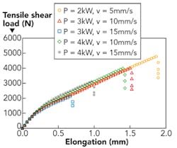
FIGURE 3 exhibits scanning electron microscopy (SEM) photos of the tightly bonded joint near the interface between CFRP and Type 304 stainless steel. Many bubbles of sub-millimeter size are irregularly formed in the matrix plastic around carbon fibers by heat conduction from the high temperature of a molten pool during laser welding. It was confirmed that the geometrical characteristics of the bubbles inside the CFRP depended on the laminated shape of the plastic and carbon fibers, as well as the level of conducted heat and the length of carbon fibers. It is understood that bubbles are more easily formed in CFRP than a normal plastic. Although the bubbles are formed just near the interface in the case of a normal plastic; in the case of CFRP, the bubbles are widely spread in the plastic matrix due to the instability between fiber surfaces and the matrix and higher heat conductivity of carbon fibers.
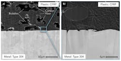
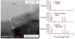
FIGURE 4 is a transmission electron microscopy (TEM) photo near the joint interface and shows TEM-EDS analysis results of respective typical points in PA matrix, oxide film on the stainless steel, and steel matrix. It is observed that CFRP is bonded on the atomic or molecular scale on a 10nm-thick chromium-iron (Cr-Fe) oxide layer of Type 304 steel. This suggests a high possibility of chemical bonding and physical (Van der Waals) bonding. Therefore, CFRP and Type 304 stainless steel could be bonded so tightly as to produce a strong joint.
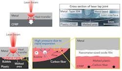
Moreover, the gas compositions inside the bubbles were analyzed with a Q-mass spectrometer by measuring the vacuum level and the mass spectra of gases emitted during the drilling of a hole measuring about 2mm in diameter from the CFRP sheet to the steel plate under a high vacuum of 7 × 10⁻⁶ Pa. As a result, the gas components inside the bubbles consist of N2 in air, H2, and the hydrocarbon series as the pyrolysis gases from the PA matrix of CFRP. The melted plastic was moved by the high pressure caused by the generation and rapid expansion of bubbles after the pyrolysis, and then flowed in any grooves or grain boundaries of the metal surface. As the bonding mechanisms deduced from all the experiments are indicated in FIGURE 5, CFRP composites were directly joined to the steel by chemically or physically bonding the melted plastic and the oxide film covering the stainless steel in addition to the mechanical anchor effect due to plastic flowed in the pits, grooves, or grain boundaries.
This laser joining technique of CFRP to metal is expected to be utilized by industry. This method was also applied to join CFRP to aluminum alloy or zinc (Zn)-coated steel, and it was confirmed that strong joints could be produced.
Acknowledgement
The authors appreciate and acknowledge Dr. K.-W. Jung, who performed joining experiments under the NEDO (New Energy and Industrial Technology Development Organization) Project.
SEIJI KATAYAMA([email protected]) is director/professor and YOUSUKE KAWAHITO is an associate professor, both at the Joining and Welding Research Institute (JWRI) at Osaka University, Osaka, Japan.