Disk lasers in the automotive and aviation industries
Adjustable nanosecond pulse lengths enable serial production
BERT KREMSER and EWA ZIOLKOWSKI
The global increase in mobility, furthered by the growing wealth in newly industrializing countries and by progressing globalization, is the driving force behind the continuous growth in the automotive and aviation industries. The resulting ecological effects such as CO2 pollution and/or climate warming, as well as the declining availability of fossil resources, advance the developments in the fields of electro-mobility and lightweight construction. This is especially evident in automotive lightweight construction, where many new materials have found their way into industrial production during the past decade (for example, aluminum and titanium alloys or carbon fiber-reinforced plastics).
Machining such materials by applying conventional manufacturing processes normally involves great effort and costs. The laser, being a contactless and wear-free tool, constitutes an excellent alternative. Typical laser applications for the above materials are the drilling of cooling holes into turbine blades made of refractory metals such as Inconel or titanium alloys, and the drilling of microholes into battery foils. In addition to the cutting of carbon fiber-reinforced plastics, the repairing of these materials has been gaining more and more in importance. For this repair process, the damaged spot is gradually removed with a laser so that a repair patch can be joined.
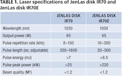
Due to the often very high melting temperature and/or heat conduction of the materials, processing them by means of a laser requires a pulse peak power in the two- to three-digit kilowatt range and focusing in the 0.1mm range. Diode-pumped disk lasers, such as the JenLas disk IR70 and JenLas disk IR70E (FIGURE 1) by Jenoptik with their high peak powers, are perfectly suited for this purpose (TABLE 1). Thanks to the flexibly adjustable pulse length in the nanosecond range and the high pulse repetition rate in the three-digit kilohertz range, these lasers are an ideal tool for both process development and optimization and for industrial application in serial production. Furthermore, the lasers stand out due to their ease of integration and controllability, great robustness, and high reliability in 24/7 operation.
Impact on the processing result
The processing quality achieved using nanosecond lasers is dependent on the heat input into the material. In this context, these lasers offer great advantages, as heat input into refractory materials like Inconel, aluminum, and titanium alloys is reduced due to the high pulse peak power and, therefore, the heat-affected zone is minimized.
The general rule is: The longer the laser impact duration, the larger the resulting heat-affected zone. In this way, a correlation between thermal diffusion length and ablation rate can be derived for an ablation process comprising the thermal intermediate steps of heating, melting, and vaporizing.
TABLE 2 shows the influence of the pulse length on the ablation rate based on the example of the single pulse ablation of an AlMg3 aluminum alloy using the disk lasers.
Where the ablation process is implemented by applying several pulses or several passes, more laser parameters (for example, power, repetition frequency, and pulse overlap) need to be taken into account. The time between pulses is usually not long enough to completely dissipate the introduced heat. In this case, the basic temperature of the material rises so that the melting and evaporating temperature is reached sooner. However, this will also result in a larger heat-affected zone and, thus, in greater damage to the material.
FIGURE 2 shows the influence of the pulse length on the time to reach the melting and evaporating temperature. At the same pulse energy, the material heats up and cools down more slowly as the pulse length increases. In this way, higher amounts of energy can be introduced into the material without causing signs of ablation on the surface. This behavior is desirable, for example, in the fusion cutting of metals within a thickness range of several millimeters or when welding plastics.
Laser drilling
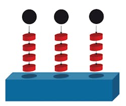
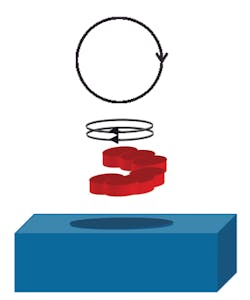
During laser drilling, the evaporating temperature must be reached on the processing surface to remove material. The material is expelled out of the upper side until the point when the hole breaks through to the bottom side. During this process, fused particles can stick to the surface or to the hole wall or, in the least wanted extreme case, close the hole again. After the breakthrough, the material is expelled through both the upper side and the bottom side. Depending on material thickness and hole size, two different drilling methods can be applied. As a matter of principle, percussion drilling (FIGURE 3) is applied for small holes where the diameter is within the range of the focus (dBohr ~ dFok/typ. <100 μm), and trepanning drilling (FIGURE 4) is preferred for medium to large diameters (dBohr < dFok/typ. >100 μm).
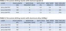
The two disk lasers are suitable for determining the influence of the laser parameters on the application result, as their pulse lengths can be adjusted. TABLES 3 and 4 show the percussion drilling results for a 1mm-thick titanium alloy (grade 5) and an 0.8mm-thick aluminum alloy (AlMg3) applying the two lasers. With a focal diameter of approximately 50μm, the attained hole diameter measures approximately 70μm and very high edge steepness values inside the hole (taper angle) of <1.1° can be achieved.
At otherwise constant laser parameters, drilling rate and taper angle are significantly determined by pulse length and pulse repetition rate, hence, by the resulting duty cycle. As shown in TABLES 3 and 4, the processing speed increases as the duty cycle grows. At the same time, however, the accumulation of debris on the surface increases and a larger heat-affected zone is recognizable.
Applying shorter pulses and a constant pulse energy (higher peak power), a smaller heat-affected zone is formed and less debris is generated, as less material is in the liquid phase and the material is vaporized immediately. Quality can be optimized through shorter pulses, whereas higher drilling rates can be achieved through longer pulses. Thus, the adjustable pulse length enables users to optimize their processes as required by the respective application.
Two drilling methods are shown below based on the examples of a nickel alloy and titanium. When drilling a hole with a diameter of 2mm through a 6mm-thick nickel alloy (Inconel) by way of trepanning drilling, the drilling process will take approx. 30s—for example, 0.03 holes/s can be drilled (FIGURE 5). When drilling a hole with a diameter of 100μm through a 1-mm-thick titanium sheet (grade 5), up to 1400 holes/s can be achieved applying the percussion drilling method (FIGURE 6). Compared to machining the material with a picosecond laser, higher drilling rates can be achieved while attaining a good hole quality at the same time.
FIGURE 6. Micro holes through titanium (grade 5) applying percussion drilling.
Engraving
When it comes to engraving, the processing result is determined by power, pulse repetition rate and length, hatch distance, and overlap. In case of a large overlap, the processing speed is lower and, thus, roughness is lower as well. Optimal laser and process parameters need to be identified for each material depending on the respective quality requirements.
In the example examinations, an aluminum alloy (AlMg3) and a nickel alloy (Inconel) were machined at different pulse repetition rates using the JenLas disk IR70, applying short and long pulse lengths (TABLES 5 and 6).
It is obvious as well that long pulses (1000–1600ns) are suitable for quick processing, while shorter pulses (200ns) generate a smaller heat-affected zone and, consequently, result in higher quality. The high pulse energy is decisive for the high productivity. The melting and evaporating temperature is reached quickest when long pulses and high pulse energy are applied.
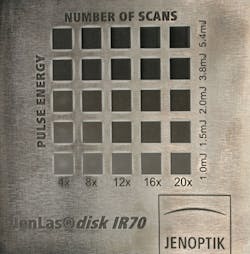
The engraving example in FIGURE 7 shows the impact of the pulse energy in dependence on the number of laser passes based on the example of aluminum. At the end of processing, surface roughness can be improved by way of a final cleaning and polishing step—by performing a processing step involving low pulse energies and a high pulse repetition rate.
Summary
Application tests with metals show that the productivity of both the ablation and the drilling process is improved by high pulse energies in the millijoule range and by pulse lengths in the range of several hundred nanoseconds. However, in the case of short pulse lengths and high pulse peak power at constant pulse energy, optimal quality is achieved in terms of the processing result. Due to the flexible setting options, the laser parameters of the JenLas disk IR70 and the JenLas disk IR70E can be adapted to the requirements of the respective application very well, and the result can be optimized with regard to productivity and quality. Thanks to their flexibility and design suitable for industrial use, these lasers are a fit for both process development and industrial application within the scope of serial production. When it comes to metal microprocessing in the automotive or aviation industries with quickly changing requirements following the respective machining task, these lasers are the preferred tool.
BERT KREMSER([email protected]) is a product manager and EWA ZIOLKOWSKI(ewa.ziolkowski@ jenoptik.com) is a laser application engineer, both at Jenoptik Laser GmbH, Jena, Germany.
