Manufacturing specimens made by direct powder deposition
Laser cladding hardware has utility in additive manufacturing
PAVEL KHAZAN, MALTE STROH, HANNES FREIßE, and HENRY KÖHLER
Direct powder deposition (DPD) methods are based on laser cladding—a process introduced and patented in 1976 [1]. The development of the laser cladding process was focused on improving surface characteristics of components. In the 1990s, a number of derived methods for additive manufacturing of three-dimensional structures using principles of cladding were introduced, patented, and are available as turnkey commercial solutions. The main principle of the process is the use of a processing head capable of bringing the powder stream, the shielding gas, and a laser heat source to a substrate, and then melting the powder as well as the surface of the substrate to create a structure from the powder material.
While equipment for laser cladding itself is comparatively inexpensive and hence also affordable for small and medium enterprises, turnkey systems for 3D printing are much more expensive. The current work describes the way of using cladding hardware for additive manufacturing.
Investigating material properties
Tensile test specimens made of Deloro Stellite 21 powder were generated on a S235JR substrate plate. Besides the proof of feasibility, the main goal was to investigate mechanical properties of such materials. The process involved a Trumpf TruDisk 8002 disk laser with λ=1030nm and a Precitec YC50 processing head with coaxial powder supply. Argon was used as process and shielding gas. The movement of the processing head relative to the substrate was enabled via a 3-axis computer numeric control (CNC) controlled by a PA8000 control unit, which uses G-code as a programming language.
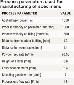
Usually, path planning requires specialized software, which is provided by a distributor of a commercial 3D printing system, where software developed for preprocessing of 3D objects for selective laser melting—VisCAM RP4.0 by Marcam Engineering—has been used. After extension with laser cladding-specific commands, a generation of G-code, including laser power and movement control compatible with a PA8000 control unit directly from CAD data, was possible. Process parameters leading to a stable process are noted in the TABLE, while FIGURE 1 shows the applied process chain.
To investigate material properties of manufactured specimens, tensile test specimens with 0°, 45° (alternating), and 90° orientation of the path relative to the longitudinal axis of the sample were built. A build-up rate of 0.85cm3/min, as well as 35-percent powder efficiency, was achieved. However, it was possible to increase the power usage by powder recycling. Generated samples were machined by means of milling and deburring, followed by tensile tests as well as metallographic investigations.
Results
Different processing angles lead to different path lengths. These lead to different thermal cycles that yield high porosity, presence of cracks, as well as the preferred direction of dilution for 0° and 90° angles, while the specimens made with 45° angles are basically pore- and crack-free. Young's moduli show no significant deviation with respect to the path orientation lying between 193 and 213GPa and thus being approx. 20 percent less than cast Stellite 21 material with about 250GPa. Ultimate tensile strength shows significant influence of path orientation, with 851MPa for 0°, 803MPa for 45°, and 738MPa for 90°, which is for each direction higher than cast material at 710MPa. For all cases, almost no plasticity area could be identified on the stress-strain curve.
Overall, it can be shown that the usage of common hardware for 3D manufacturing of large specimens is possible if the software supports the specifics of the process and is able to generate G-code compatible with the control unit. With the help of standard test specimens, better understanding of material evolution during laser cladding becomes feasible. Effects of anisotropy are best handled using 45° alternating path orientation (FIGURE 2).
ACKNOWLEDGEMENTS
Results presented in this work have been originally published in Advanced Materials Research, 1018, 525–532 (2014), where more in-depth information can be found.
The authors thank Deutsche Forschungsgemeinschaft DFG for funding the project VO 530/61 "Dauerfestigkeit von Mittelschnellläuferkurbelwellen nach Rekonditionierung durch Laserstrahlbeschichten" ("Fatigue strength of medium-speed crankshafts after reconditioning by laser cladding"). Furthermore, the authors thank Stiftung Institut für Werkstofftechnik Bremen (IWT) for the support in final machining of specimens.
REFERENCE
[1] D. S. Gnanamuthu, Cladding, U.S. Patent 3952180A (1976).
The authors are all with BIAS - Bremer Institut für angewandte Strahltechnik, Bremen, Germany. Pavel Khazan can be contacted at [email protected].


