Forming a new material
Fiber Metal Laminates (FML), sometimes referred to as Metal Laminate Composite materials (MLC), a combination of thin metal sheets and fiber reinforced composite layers (see Figure 1) are of significant interest to the aerospace industry. Their high fatigue resistance and high strength yet lightweight construction of parts offer significant weight reductions and hence a reduction in operational costs of new large commercial aircraft such as the Airbus A380 and the proposed ultra-efficient Boeing 7E7. Military applications are also being considered such as the Joint Strike Fighter program.
For the A380 an FML called GLARE (Glass Reinforced Aluminum Laminate), supplied by Fokker Aerostructures, is to be used in the construction of the outer skin panels for the upper fuselage at the front and rear of the plane, where it represents a weight savings of about 500–800 kg. The metallic layers of the panels are pre-formed prior to lay-up and curing with the composite. In a move away from the traditional rivet-based fixturing, the GLARE panels are spliced and bonded seamlessly with no break in the fiber reinforcements, and the stringers are adhesively bonded to the panel surface. The required openings for windows and doors are milled out of the formed panel; a fusion process is not possible due to the presence of the composite.
Airbus decided to use GLARE, an aluminum glass fiber laminate, on its 650-seat A380 as an alternative to aluminum. Research has shown it has benefits over both aluminum and glass fiber reinforced composites, especially in fatigue and impact. By the selection of different types of laminate components, together with the possibility to vary the volume fraction of the composite and fiber orientation, a wide range of material properties of the resultant product can be produced. The FML materials under investigation in this work have been developed in the Materials Science Division of the University of Liverpool. Work is ongoing to develop materials, or material combinations, that require much shorter manufacturing times and have a superior impact resistance.
The materials are manufactured using Teflon-coated steel molds where the laminates are laid-up, using a polypropylene interlayer to adhere the pre-preg composite material to the metallic layers. The molds are then heated and a pressure applied to the upper surface to melt the bonding layers. Larger panels can be processed in large autoclaves.
FML materials can be formed conventionally into components, however their high strength and laminated construction limit minimum bend radius and they need a metal layer within the laminate to deform it once constructed. The material has a considerable anisotropy and its axes change direction as any forming operation proceeds. Also, in laminated parts the layers can slip over one another. Another factor is the large residual stresses that remain between each layer after manufacturing that can produce considerable distortion in a formed part. As a result, research is ongoing at Liverpool in the use of laser forming with FMLs to demonstrate the potential of the technique as a manufacturing tool for FML materials, either as a means of direct manufacture or a means of alignment and distortion removal.
Laser forming has become a viable process for the shaping of metallic components, as a means of rapid prototyping and of adjusting and aligning. The laser forming process is of significant value to industries such as aerospace, automotive, shipbuilding, microelectronics, and industries that previously relied on expensive stamping dies and presses for prototype evaluations. In contrast with conventional forming techniques, the laser method requires no mechanical contact and thus promotes the idea of "Virtual Tooling." It also offers many of the advantages of process flexibility associated with other laser manufacturing techniques.
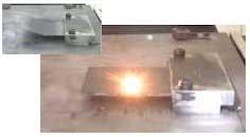
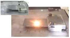
Laser forming can produce metallic, predetermined shapes with minimal distortion. The process is similar to the well-established torch flame bending used on large sheet material in the shipbuilding industry but with more control of the final product. The laser forming process introduces thermal stresses without melting into the surface of a work piece as a de-focused high-power laser beam is passed over it (Figure 1). These internal stresses induce plastic strains, bending or shortening the material, or result in a local elastic plastic buckling of the work piece depending on the mechanism active. Typically, a few degrees per pass can be achieved (Figure 1).
A number of FML types were investigated, both thermoplastic and thermosetting fiber-reinforced composite layers combined with thin section Al2024 (0.3 mm and 0.9 mm gauge), using a number of different lay-up configurations (see Figure 2).
The composites investigated include a thermoplastic-based glass reinforced polyamide, self-reinforced polypropylene, glass fiber reinforced polypropylene, and a thermosetting glass fiber reinforced epoxy (GLARE type). The thickness of these materials varied from 1.38 mm to 3.1 mm depending on the thickness and number of layers used. Energy parameters consistent with the temperature gradient mechanism (TGM) were used throughout the study. For this mechanism, the high thermal gradient causes an asymmetric plastic compression through the thickness producing a bending moment about the scan line; this results in a bend towards the laser.
Because the TGM causes a plastic compression of just the upper surface layers of a solid metallic section, it was thought that by forming, by TGM, the upper aluminum layer alone, a moment could be generated sufficient to bend the material section. By tuning the processing parameters for a high thermal gradient across the thickness of the upper layer, it was possible to produce a significant bend in the FML materials without any melting or damage.
Figure 3 shows the results for a self-reinforced polypropylene based FML using a CW CO2 laser. The thickness of the 2/1, 3/2, and 4/3 lay-ups is 1.38mm, 2.35 mm, and 3.1 mm, respectively.
It can be seen that, as would be expected, the achievable bend angle falls with increasing numbers of layers for the same energy parameters. This is consistent with the increase in material strength and increasing ratio of depth of material to available depth of plasticized zone. Hence, the moment generated in the upper surface produces less overall bend. Additionally, what can be noted from this result is the relatively small energy input required to bend the material.
It is also possible to laser form a GLARE-type material. This material is a laminate of 2024-T3 aluminum and glass fiber reinforced epoxy, a thermosetting matrix composite. Additionally, as the laser laminate forming process relies on the bending of the upper layer alone, it was found that increasing the thickness of the Al2024 layers to 0.9 mm improved the laser formability of the material by increasing the achievable moment. The result on a 2/1 GLARE FML at various traverse speeds can be seen in Figure 4.
Here, the rate of forming per pass is governed by the energy input: the slower the traverse speed for the same power and spot size, the higher the energy input and hence the higher the bend angle per pass.
Although there is an upper limit to the degree of bending without damage or delamination of the material, consistent with the problem of a minimum achievable bend radius, it can be seen that, as with the previous result, there is sufficient available distortion per scan line for multiple scan line large radii bends. There is even the capability to use the process to align and remove distortion post-conventional forming or post curing. In order to demonstrate this, a system was set-up for the closed-loop laser forming of a 240 × 80 mm coupon of 2.3 mm 2/1 GLARE FML into a large radii part-cylinder using a series of stepped single bends of no more than a few degrees each. The bend angle was monitored using a laser rangefinder and the bend angle rate per pass was controlled via the traverse speed. As the desired angle approached, the traverse speed increased so as to avoid overshoot. The formed component can be seen in Figure 5; the processing time was 10 minutes.
Further study is planned on using laser forming to pre-bend the metal layers prior to curing to achieve larger available deformation and possibly more complex 3D surfaces.
S.P. Edwardson, G. Dearden, and K.G. Watkins are with the Laser Group (www.lasers.org.uk) and W.J. Cantwell is with the Impact Research Centre, Department of Engineering, all at Liverpool University, UK. Contact Stuart Edwardson by e-mail: [email protected].


