Wire feed systems for laser welding
Increasing importance is being attached to the energy consumption of transportation vehicles during the process of their design. Light metals play a special role in weight reduction. The civil aviation engineering industry, in particular, is coming under increasing pressure to advance its products to meet the growing requirements of airlines for better performance on the one hand and lower costs on the other [1]. In addition to new design principles, the task is to develop production processes incorporating appropriate joining techniques [2].
The laser beam, as a welding tool, is characterized by high-energy density at high processing rates. Energy is applied at a high concentration and spatial precision, thus permitting a tight joining of seam sidewalls with very little warping and without any cold-starting problems [2,3].
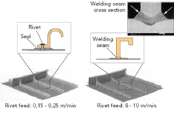
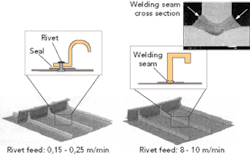
Integral structures welded in this manner also are more resistant to corrosion than riveted structures, due to an absence of gaps, Figure 1 [1]. However, welding of aluminum alloys poses specific problems, that need to be countered appropriately. Worthy of mention are physical properties such as high thermal conductivity, high coefficient of thermal expansion, and low viscosity of the fused metal.
The resulting process is highly unstable and leads to imperfect seams. Additional aspects of a technological nature include the high-temperature tearing sensitivity of certain alloys, a tendency to form pores, and surface oxidation [2,3]. These factors render a requirement for modifications and parameter variations that can improve the laser-beam welding process. A method involving the use of filler wire is discussed individually in the following.
Operating principle
Laser-beam welding with external wire feed requires an exact positioning of the laser beam and filler wire. In either case, the reference point is where the center axis intersects with the surface of the base material. The wire feed angle also notably influences the welding result[4]. Needless to say, extremely high precision needs to be ensured at high welding rates and high wire feed rates, thus placing special demands on the wire feed system.
The laser processing head needs to have a low dead weight and be furnished with a compact, slim wire feed unit to permit easy integration into the overall concept. Basically, the wire feed system has a modular design, allowing the filler wire to be fed by means of one or more drive units depending on the application involved. Suppliers usually offer filler wire of a diameter between 0.8 and 1.6 mm on a reel with a diameter of 300 mm, although larger diameters and barrel-type packaging also are quite common.
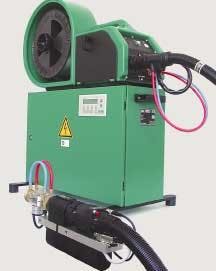
Factors related to size and weight therefore rarely allow the store of filler metal to be installed in the immediate vicinity of the laser optic system. This raises the need for a system that feeds the filler wire over long distances to the joining location. Accordingly, most welding applications make use of a design incorporating two drive units, Figure 2.
This wire feed system operates on a principle whereby the front drive assigned to the laser optic unit (Figure 2, front) maintains the wire feed rate at the set value while the rear drive (Figure 2, rear) on the store of filler metal supplies the front drive with an adequate amount of filler wire. This fully decoupled type of control is termed PUSH-PUSH mode. The main advantage of this technology is that the front drive has neutral-force access to the filler wire so that it can concentrate entirely on controlling the wire feed rate for the welding process. The rear, torque-controlled drive is responsible for feeding the filler wire forward at an adequate rate.
To prevent the filler wire from buckling, a maximum torque is set in accordance with the employed wire material, wire diameter, and feed distance. Limitation of the torque output by the motor consequently also limits the feed force via the drive rolls. The front, speed-controlled drive takes out the filler wire from the wire conduit hose in the precise quantities required for the process. This results in a constant wire feed rate reproducible at all times between the two drive modules, irrespective of torch set torsion and bending. Very low frictional forces result in very low wire feed forces. Furthermore, the contact pressure exerted by the drive units on the filler wire is minimized so as to prevent it from deforming.
This makes it possible to optimize the dimensions of the front drive (compact, lightweight) without impairing component accessibility. In the case of thin, soft wire used in the aerospace industry, the size of the front drive plays a significant role in light of the requirement to minimize the distance between the drive and the joining location to ensure stable wire feed. The wire feed system is completed by a programmable control module permitting optimal matching within the requirements of the laser welding application in terms of operation and process monitoring.
Laser/cold-wire technology
Feeding filler wire to the weld pool can be accomplished using several techniques. The one most commonly used today involves cold-wire. Aluminium alloys requiring welding are a source of motivation to employ a laser beam fed with a metal filler wire.
This type of material can lead to a formation of hot cracks during the cooling phase, caused by shrinkage of the fused metal as the temperature drops. This effect is compensated by the filler metal, which is used to specifically modify alloy composition along the welded joint [5,6,7]. The standardized interface of the wire feed head for cold-wire laser welding allows it to be coupled easily and quickly to the front drive, Figure 3 (a). The compact design nevertheless permits an integration of liquid cooling. Shield gas is fed co-axially and emerges concentrically around the wire feed tip. This is the only supply required.
This design not only ensures perfect shield gas coverage, but also offers enough space for installing the various seam tracking systems. An adjustment gauge makes it possible to check, at all times, the wire feed head for accuracy of the filler wire feed to the laser beam's focus.
The unit comprising the wire feed head and drive can be adapted easily to all common laser processing heads and permits alignment with the laser beam.
Laser/hot-wire technology
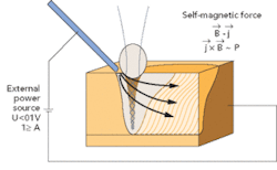
Experience gathered with laser/cold-wire technology formed the basis for developing a process variant in which case the filler wire is used as a medium for supplying current to a point in front of the vapor capillary of the base material [2]. The aim of this variant is to further increase process stability and improve seam formation by means of electromagnetic body forces. The magnetic fields are generated by self-induction arising from the current flowing through the weld pool [2]. The advantage of this method is an absence of thermal stresses from additional energy sources, Figure 4. As shown in the sketch, this leads to a current density distribution which, together with the self-induced magnetic field, generates a resultant force vector from top left to bottom right. The weld pool is steered downward to produce a much deeper and finer seam, Figure 5.
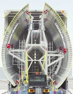
Further advancement of laser beam welding with filler metal will foreseeably generate additional potential, especially in the field of aerospace engineering. Other investigations are concentrating on an extension of current applications to the lateral and top shells of the aircraft fuselage to realize economic benefits compared with conventional rivet joints. Skin-to-skin and composite joints also should pose interesting challenges.
Characteristic profiles such as those represented by real CNC axes will be needed for future wire feed systems to stay abreast of these developments and remain adequate as modules.
Dirk Dzelnitzki is technical director with Dinse G.m.b.H., Hamburg, Germany. He can be contacted by email at [email protected].
References
- Schneider, K. and J. Schumacher: Laser technology—A key competitive aspect of modern structural engineering in the civil aviation industry. Laser Beam Joints, Steel Engineering, Volume 19, BIAS Publisher, Bremen 2002, p. 5, 9.
- Hügel, H. and F. Dausinger: Laser beam welding of aluminium material—problems, solutions, and potential applications. Laser Beam Joints, Steel Engineering, Volume 19, BIAS Publishers, Bremen 2002, p. 202, 211, 212.
- Neubert, J. et al: Industrial robot system for material processing with the latest diode-pumped solid-state laser robots — Automatic Welding Production Techniques, DVS Reports, Volume 217, DVS-Publishers Ltd., Düsseldorf, 2002, p. 105.
- Posch, T. and T. Christiansen: Investigations of parameters influencing laser brazing of body sheet metal. Laser Beam Joints, Steel Engineering, BIAS Publishers, Bremen 2002, p. 337.
- Schumacher, J.: Experiences gathered during the introduction of laser-beam technique for the aircraft industry. Laser Beam Joints, Steel Engineering, BIAS Publishers, Bremen 2002, p. 249, 252, 255.
- Neye, G. and J. Schumacher: Welding in the aerospace industry—from electron-beam to laser-beam welding. Welding and Cutting 2003, DVS Reports, Volume 225, DVS Publishers, Düsseldorf, 2003, p. 64.
- Harlfinger, N.: Bombardier Transportation subproject: Laser-beam welding of light structures during the manufacture of rail vehicles. Optical Technologies, Volume 2, Laser Systems for Innovative Lightweight Construction, VDI Technology Centre, Düsseldorf, 2003, p. 64.
