High-speed contour welding
SHADOW welding proves its benefit in microwelding with Nd:YAG lasers
Since the early days of industrial laser processing, various microwelding strategies have been developed using pulsed solid state Nd:YAG lasers. These strategies include spot welding with formed pulses adapted to the melting dynamics of the melt pool and the metallurgy during the cooling phase. [1-3] Modulated pulses, so-called metallurgical pulses, [2] seem to influence convection in the melt pool and consequently the mixing of similar or dissimilar metals. When welding contours, the pulsed lasers offer the concept of a classical seam weld: modern pulsed Nd:YAG lasers offer online controlled, high peak power up to 10 kW during the pulse duration, which can reach 100 ms resulting in pulse energies of more than 100 J. These laser parameters in combination with spatial beam forming and distribution optics, such as ring optics, or fast beam distribution optics, such as galvos, allow for new welding strategies. [2] One of these strategies, SHADOW, for fast, single-pulse contour welding, is the subject of this article.
Principles of contour welding
SHADOW, which stands for Stepless High Accurate and Discrete One Pulse Welding, was created by the Fraunhofer Laser Institute [1] and is simply contour welding within the duration of a long (up to 100ms) laser pulse. This laser radiation is applied directly via focusing optics or fiber to the workpiece. The advantage of the direct beam is the possibility to create microseam welds with spots smaller than 20 microns, leading to accurate, high aspect ratio (depth/width) welds with little heat-affected zone (HAZ).
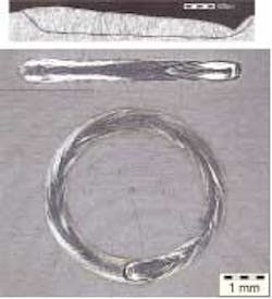
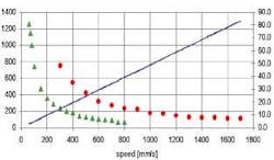
The disadvantage is that the welding depth of the contour is not constant due to changes in beam quality during the solid state laser pulse. Contours that allow spot sizes greater than 50 microns can be welded via fibers and focusing optics. Due to the constant beam quality of the “fiber beam,” the SHADOW weld exhibits an almost constant depth and width of the weld geometry (Figure 1). For contour welding within pulse durations of up to 100 ms (such as that available with LASAG’s SLS or FLS C lasers), fast movement of the beam has to be achieved by galvos, CNC, or rotating axis depending on the geometry of the contour. The limit of contour length and welding penetration is dependent on pulse duration, pulse power, and spot and is shown in Figure 2. It is clear that the application of this strategy is limited to small geometries.
Benefits of contour welding
Contour welding offers numerous benefits:
• Welding speed-Obviously it is a fast weld, with speeds in the range of 1 meter per second (similar to high-power CW lasers), as compared to the conventional seam welding speed achieved with pulsed lasers, which is in the range of a few meters per minute. This limitation with pulsed lasers is determined by the available pulse frequency and average power, the spot size, and the spot overlap. Figure 2 shows the single pulse welding speed for stainless steel in terms of welding depth and pulse power. Also indicated are the maximum contour lengths for a required penetration depth.
• Quality of the weld-Investigations by several groups [1, 2, 4] show that the optical appearance of the welded contour is similar to the surface of a CW laser weld, as can be seen in Figure 1. When the peak power is high enough to reach the threshold for key-hole welding, the weld surface shows instabilities similar to humping, which is observed with high-power CW lasers.
• Thermal side effects-The fast speed in combination with the small spot diameters at multi-kilowatt power reduces the thermal side effects such as HAZ or deformation compared to standard seam welding. This is understandable by keeping in mind that in classical seam welds with pulsed lasers, energy is locally deposited in milliseconds while in SHADOW this is done in microseconds, so the heat has less time to diffuse from the melt pool into the neighboring material.
• Metallurgy-It appears that the small spot in combination with the high welding speed leads to a favorable dynamics of the melt in the “linear” weld pool. This can lead to a better metallurgy and more favorable mechanical stability, especially when joining similar or dissimilar metals that tend to show cracks or brittleness in the weld [2, 5] with standard seam welding. Measurements show that the surface temperature in the moving spot is quite constant compared to seam welding with overlapping pulses where the temperature is fluctuating locally depending on overlap and pulse energy. One has to keep in mind that the time scale for convection dynamics and heat diffusion is in the same range as the welding speed, while conventional seam welding with millisecond pulses typically is 10 times slower. All this will lead to modified dynamics during melting and cooling and influence the metallurgy.
Microwelding applications
Until now the aforementioned advantages and benefits-mainly the lower thermal side effects and the modification in metallurgy-have been proven for various applications.
One of the first applications was watch parts that are sensitive to deformation, such as balancers, watch indicators, [1] and other parts consisting of copper alloys such as CuBe2, Ms61Pb, German Silver, or CrNi alloys. Compared to standard seam welding the improvement with respect to thermal problems is clearly demonstrated. For medical instruments and implants, biocompatible metals such as NiTi, stainless steel, Ti, TiAl, or platinum can be joined. This allows a functional selection of the material. The image on the right in Figure 3 shows two thin (0.1mm) stainless steel tubes with an outer diameter of 3 mm that have to be butt-welded vacuum-tight. Heat deformation has to be avoided to guarantee the reliable pointing stability of the device. A 30ms pulse was applied with 5 J and a rotation of 2150 rpm. The image on the right in Figure 3 shows the shadow welding of two different NiTi tubes.
In many micro-electronic joining tasks using copper alloys, where welding penetration is limited to a few hundred microns but high mechanical forces, reliability, and limited heat damage are required, SHADOW seems to be a proper welding strategy and could be an alternative for soldering. SHADOW has been successfully applied [4] to reliable hermetic welding of very thin membranes (< 20 microns) for sensors, which turns out to be especially critical with respect to deformation and proper fixture.
Summary
SHADOW welding has proved its benefit in microwelding with Nd:YAG lasers. The procedure shows its advantage where thermal side effects should be minimized, especially deformations during and after welding or thermal change of the crystallographic, magnetic, or other material properties in the HAZ near the welding zone. It is also shown that in many cases, joining similar or dissimilar metals that show unreliable results in standard laser welding can be successfully welded. This opens possibilities in replacing soldering with lead solder and in joining metals, selected according to required functions and not according to their weldability.
Ulrich Duerr is manager of applications at LASAG AG, Thun, Switzerland (www.lasag. com).
REFERENCES
1. Kramer, T., A. Olowinsky, and F. Durand, “SHADOW-A New Welding Technique,” Proceedings of SPIE, Vol. 4637 (2002), p. 545.
2. Duerr, U., R. Holtz, M. Jokiel, R. Liebers, and D. Lavoie, Proceedings of the 23rd Int. Congress on Applications of Lasers and Electrooptics, 2004.
3. Amorosi, S., Th. Sidler, R.P. Salathe, H.P. Schwob, and J. Hertzberg, Journal of Laser Applications, Vol. 16, No.3 (2004), p. 134.
4. Hanebuth, H., DVS-Berichte Band 225 (2003), p. 155.
5. Klages, K., A. Gillner, A. Olowinsky, S. Fronczek, and A. Studt, Proceedings of SPIE Vol. 5063 (2003), p. 56.


