Welding from a distance
MICHAEL BEMBENEK
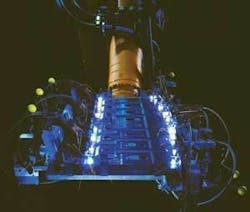
Remote laser welding (RLW) is a relatively new technique based on an old principle where galvo-mirrors (or mirrors) move (scan) a focused laser beam over the workpiece from a distance of approximately 0.5–1 m for solid-state RLW systems and about 1.5 m for CO2 RLW systems.
Scanning occurs over an area ranging from a fraction of a square meter to a few square meters, depending on galvo-mirrors being either in a fixed or movable arrangement. The speed with which scanning occurs over the workpiece is in the range of milliseconds per meter, which significantly reduces the in-between-weld repositioning times. This is one of the great cycle time advantages of the RLW principle.
Welding speed is a function of laser power at the workpiece, material gauge, joint fit-up, and type of material to be welded. Thus it is possible to make three welds per second, which translates into six times the speed of traditional resistance spot welding. Normally it takes two seconds to make one resistance spot weld (RSW). Furthermore, it is almost impossible to achieve that great efficiency with traditional RSW technology.
Additionally, the shape of the weld can be programmed in a variety of geometrical shapes and figures such as circle, sine wave, open circle, and spiral, giving laser welding further structural advantage over conventional spot and MIG welding. RLW has other advantages, processing efficiencies, and flexibilities not seen in traditional assembly-line methods like those pioneered by Henry Ford.
First developments
The first advance of the technology began with the development of high-power lasers able to generate beams focusable to a small spot that assured sufficient power density at the workpiece for keyhole welding from a significant distance.
An early contribution to development of RLW came from John Macken, founder of Optical Engineering (Santa Rosa, CA), whose unique 4kW laser using magnetically enhanced electrical discharge allowed the welding of sheet metals from a previously unseen distance.
The first industrial RLW designed primarily for the automotive industry was built in 1999 as a result of a 50/50 partnership agreement between Aetna Industries Inc. (Centerline, MI) and Rofin-Sinar (Plymouth, MI.) This was made possible because of the availability of Rofin’s slab laser with excellent beam quality and the understanding from both parties that this solution could be widely applied in the automotive industry.
The Aetna/Rofin system adopted transmissive optics for beam focusing, as opposed to reflecting mirrors. Further development of this system resulted in full industrial application of RLW when Utica Enterprises (Shelby Township, MI) and Optical Engineering introduced its system to Chrysler Corp. manufacturing plant.
The road to industry
The two basic questions upon which the future of RLW hinged were: an interest from the automakers and technical issues associated with welding zinc-coated materials with the laser beam. Automakers, pushed by competition and rising cost problems, were searching for better, more economical manufacturing solutions, floor space reduction, and flexible manufacturing methods that were less expensive and allowed for quick changeovers. The latter has become more and more important, as the volumes of manufactured units per model have dropped significantly.
All the major players and some non-automotive related companies visited Aetna or Rofin to watch the sparks gushing out of coupons and prototype parts under RLW unit. In general, at least verbal acceptance was there.
Welding galvanized body parts with laser was a much more serious problem than thought, acting as a drag on the application for many years. Even now the opinions are mixed, with the prevailing theory that welding with laser two galvanized sheet metals pressed tightly against each other is either not possible or at least hardly acceptable. Both positions are justified because there is no way to defy the law of physics and prevent zinc vapors trapped between the sheet metals from erupting through the pool of melting steel to cause porosity and a not very attractive looking weld. Also existing weld standards developed for resistance welding didn’t allow, with rare exceptions, the admission of laser welds to the body-in-white manufacturing process.
A few methods had been developed as a way to overcome zinc vapor problems, but the solution of providing the “escape route” for zinc vapors have in several variations—such as incorporating strategically placed surface distortion of the welded materials or smart clamping of the welded parts—opened the door to some industrial application of RLW.
Additional methods include bonding zinc with other materials such as copper, by placing copper foil or copper paste between galvanized sheet metals to form the alloy during the welding process in order to reduce zinc vapor expulsion.
Alternate solutions address keyhole dynamics by using oscillations, multiple laser beams instead of one, or by applying an oblong-shaped laser spot and variable beam incidence onto material.
It seems, however, that the problem is here to stay, and until a “laser friendly” material or material coating is developed, the companies will have to work around it.
The knowledge that laser welding of galvanized sheet metal, in spite of its porous appearance, is as strong as or even stronger than the resistance spot weld made it logical to relax or change traditional welding standards and implement proper manufacturing and inspection-monitoring mechanisms to be on the winning side.
Therefore, it was not a total surprise when, at a 2004 laser conference in Dearborn, MI (Automotive Laser Applications Workshop-ALAW), the director of joining processes at Volkswagen Wolfsburg- Germany presented the VW Golf body, which was 75 percent laser welded.
RLW in manufacturing processes
Remote laser welding with the advantages and challenges of laser welding in general, has two major advantages over traditional laser welding with short focal length optics. As mentioned earlier, the high speed of the intra-weld beam movement contributes to a significant reduction of the cycle time. Also, the long stand-off of the focusing head permitting access to areas not accessible with short focal length welding makes Remote Laser Welding applicable in a wider spectrum of products. The fixture holding the welded assembly can be less expensive and elaborate than its traditional counterpart, but includes nozzles for shielding gas, if necessary.
RLW makes sense from a technical and financial point of view when changing to another production program, because only the fixture needs to be removed and replaced while the laser system needs only to be re-programmed.
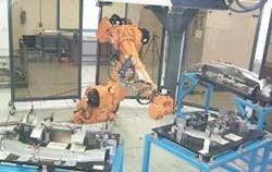
Figure 1 shows the Flexible Welding Cell concept presented at Aetna’s Laser Laboratory in 2000. Here, the robot is located in the center of a half-circle on which perimeters are three stations holding fixtures with multiple parts on each fixture. The operators are manually loading and unloading the parts, then the fixtures are picked up by the robot arm equipped with quick disconnect and presented to the laser beam of the remote welding system located above on the gantry. This kind of solution results in a large increase of the RLW welding envelope and allows for placing laser welds inside some parts through the holes in the fixture base.
The fixtures are interchangeable with the stations and can hold the parts from different programs, which makes the system a really flexible production tool.
Since then, new developments of Remote Laser Welding have brought to the market many other interesting solutions. Except for some successful applications in various body-in-white applications, RLW is being applied or gaining attention in different areas such as: instrument panel, assembly reinforcements of bumper cross member, rear seat panel, side impact members, engine cradle, tubular products, tailored blank patchwork, and so on. The progress is also visible in appliance and other non-automotive industries.
Unfortunately, from the applications side we tend to use new tools just to replace the old ones, without taking advantage of unique possibilities that the new tools often bring. Laser technology, especially Remote Laser Welding, gives the manufacturers a cost-effective replacement tool for welding and opens areas for new designs and better, structurally improved final product.
Reduction or removal of flanges traditionally required for spot welding, one-sided access, “shooting” a laser beam through holes and narrow spaces, elimination of design gaps, better material utilization, and better structural properties are some of the improvements that can be realized.
As for now, designing the product with lasers in mind is the area of manufacturing process waiting to be implemented by the design community.
Recent developments
Currently there are two prevailing RLW concepts available on the market, with the major differences along the division line between solid-state and CO2 lasers, particularly beam delivery capabilities.
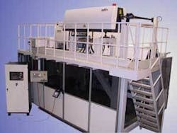
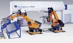
CO2 lasers require mirrors to direct the beam from the resonator to the scanning head. Therefore the distance between those two has to be kept as short as possible to avoid external environmental conditions having an impact on the beam (vibrations, contaminations, “beam conditioning” hardware required at larger distances). For this reason the Remote Laser Welding System is designed as a compact unit, mostly a gantry type, carrying a laser resonator on the top of the gantry and the scanning unit underneath. A typical example of such a solution is Rofin’s RLW system (see Figure 2). Figure 3 shows TRUMPF’s version of a CO2 RLW system.
Because the wavelength of solid-state lasers like the popular YAG allows delivery of the beam using fibers, the resonator can be located at the distance of hundreds of feet from the scanning head. In this case the scanning head can be attached to the gantry or to the robot arm. The latter is the solution adapted by TRUMPF Inc.
Although the scanning envelope of robotic RLW is smaller than that of the CO2 laser because of the YAG laser’s beam quality and size of the scanning head, the total working envelope is within the reach of the robot arm. Each of these systems has it’s weaker and stronger points, but the application is the final judge. Inertia of the robot arm movement makes a total cycle time slightly longer, but the manipulation of the scanning head in three-dimensional spaces allows for welding large and complex objects from all sides. Also, the fiber solution lends itself to easy beam multiplexing and beam sharing applications.
On the other hand, the CO2 laser-based RLW offers incredibly fast cycle time, but mostly in two-dimensional planes. In order to weld the part from all sides, the part has to be rotated.
Another issue involves the different wavelengths of laser beam emitted by CO2 and YAG resonators. The reflectivity and type of the welded material can be a key factor in choosing one type over the other.
Some ideas just wait to be discovered, some remain stubbornly hidden behind our routines and comfortable status quo. Whatever the case, progress always finds a way to prevail and the path after discovery is always the same: it takes a good leader and a great team to put the idea to work. Then, the time will show its real place in the manufacturing toolbox.
It seems that RLW has found its leaders and teams in laser manufacturing companies, car manufacturers, R&D, and supplying industries and established its steady place in modern welding technology. Although it is not a silver bullet for all welding problems, it will continue finding its subsequent niches in various applications.
Developments in fiber lasers and disk lasers are opening new exciting possibilities for Remote Laser Welding.
References
- T. Klein, M. Vicanek, G. Simon, “Forced oscillations of the keyhole in penetration laser beam welding,” J. Phys. D: Appl. Phys. 29 No 2 (14 February 1996) 322-332.
- Xie, J., “Dual beam laser welding,” Welding Journal, Oct 2002, pp 223s-230s.
- M. Forrest and F. Lu, “Fundamental study of dual beam laser welding of zinc coated steel sheets in lap joint configuration with zero-gap,” ICALEO 2003.
- Dasgupta, A., Mazumder, J. and Bembenek, M., “Alloying based laser welding of galvanized steel,” Proceedings of ICALEO 2000, Laser Institute of America, Dearborn MI, October 2000.
- Dasgupta, A., Ki, H., Mazumder, J. and Bembenek, M., “Process monitoring during remote laser welding of galvanized steel,” Proceedings of ALAW, Center for Professional Development-University of Michigan, Dearborn MI, March 2002.
- C. J. Mombo Caristan, “Advanced process for high-speed-high-power laser welding,” ICALEO Conference 1996 Proceedings - Section D pp 46-53 - Laser Institute of America.
Michael Bembenek ([email protected]) is an independent laser consultant.


