Tube and profile welding
Use of slab laser enhances quality and improves competitive advantage
Christopher Pilcher
In recent years, with more attention being focused on environmental problems, automobile manufacturers have come under increased pressure to improve automobile fuel economy. Tighter and more restrictive regulations have given rise to engineering challenges in manufacturing and materials processing. Included in these trends are reduced exhaust emissions, lighter weight vehicles, and parts requiring life extension.
Advances in material manufacturing have created unique challenges in the area of stainless-steel tube production. Specifically, manufacturers are required to produce components that are lighter weight yet still maintain corrosion protection and strength requirements. In addition, automobile body space limitations have placed more emphasis on formability. Typical applications include exhaust tubing, fuel line, fuel filler, and more.
In manufacturing stainless-steel tube, a flat strip is formed until the profile becomes a round tube. Once formed, the tube seam must be welded together. This welded seam greatly affects the formability of the part. Therefore, proper selection of the joining technology is of paramount importance when creating a welding profile that meets the stringent testing requirements of manufacturing. There is little question that Gas Tungsten Arc Welding (GTAW), High Frequency (HF) welding, and laser welding have found their places in stainless-steel tube manufacturing.
HF induction joining
In HF contact and HF induction welding the equipment that provides the electrical current is independent from the equipment that supplies the squeeze pressure. Additionally, both methods can employ impeders, which are soft magnetic components located inside the tube that help focus the weld current in the strip edges.
In both cases, the flat strip is sized, cleaned, and roll formed until it reaches the welding station. Furthermore, the induction coils used in the heating process are cooled using coolant. Ultimately, some of this coolant finds its way into the squeezing process. Here a significant amount of force can be applied to the squeeze rollers in order to eliminate porosity in the welded zone: however, applying more squeeze pressure increases the weld flash (or weld bead). In addition, specially designed cutting tools are used to remove the weld flash on the inner and outer diameter of the tube.
One of the main benefits of the HF process is the ability to process the tube at very high speeds. However, typical of most solid phase forge welding methods, HF welded joints are not easy to test reliably by conventional non-destructive technique (NDT) methods. Weld flaws can be present as thin planar areas of low-strength bond, which are not readily detected by conventional methods and may not be reliable in some demanding automotive applications.
Gas Tungsten Arc Welding
Historically, tube-mills initially embraced GTAW as the joining process of choice. GTAW creates an electrical welding arc between a non-consumable tungsten electrode and the metal being welded. Simultaneously, inert gas is fed through the torch to shield the electrode, create an ionized plasma stream, and protect the molten weld pool. It is an established and understood process that results in repeatable high-quality welds.
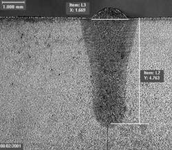
Benefits of this process include repeatability, spatter-free welds, and elimination of porosity. GTAW is considered to be a conduction process and, as such, is relatively slow. Figure 1 is a photomicrograph showing the typical metallurgical structure resulting from the GTAW process.
HF arc pulsation
In later years, GTAW welding power supplies, called high-speed switchers, allowed arc pulsation of more than 10,000 Hz. Tube-mill users were the first to benefit from the new technology where HF arc pulsation resulted in a five-fold increase in the downward pressure of the arc force over conventional GTAW. Typical benefits were increased burst strength, faster line speeds, and a reduction in rejects.
Tube-mill users immediately saw the need for reducing the welding profile generated by the joining processes, however, the welding speeds were still considered to be relatively slow.
Laser welding
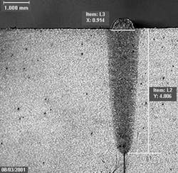
In all tube welding applications the edge of the strip becomes molten and solidifies as the tube is squeezed together using the pinch rollers. However, unique to the laser welding process is its high-energy beam density. Not only does the laser beam melt the top surface of the material, it creates a keyhole resulting in a very narrow welding profile.
Power densities below 1 MW/cm2, such as GTAW, do not produce the necessary energy density required to produce the keyhole process. Subsequently, the resulting welding profiles for non-keyhole processes are wide and shallow. The precision of laser welding results in higher efficiency penetration and translates to the reduction in grain growth and better metallurgical quality. On the other hand, the higher heat input and slower cooling process of GTAW results in a coarser welded structure.
In general, the laser joining process is determined to be faster than GTAW with equivalent scrap rates and better metallurgical quality, resulting in higher burst strength and higher formability. When compared with HF welding, the laser processed material is relatively oxide-free resulting in lower reject rates and higher formability.
Effect of spot size
In stainless-steel tube mill welding the depth of the weld is set by the thickness of the tube. Subsequently, the goal has been to increase formability by minimizing the width of the weld while achieving maximum speed. In selecting the optimum laser one cannot only consider the beam quality but must consider the accuracy of the tube mill as well. Moreover, there is a limit to the minimization of the spot size before the dimensional inaccuracies of the tube mill come into play.
The typical dimensional difficulties found in tube mill welding are numerous, however, the key components that specifically affect the welding are found in the presentation of the seam to the weld box, and more specifically the weld rolls. Once the strip is formed and is ready for welding, the seam is characterized by strip gap, high/low mismatch, and seam center line variation. The gap influences how much material is used to form the welded pool as presented to the pinch point rolls. Too much pressure could result in an excess of material on top of the tube or on the inner diameter. On the other hand, high/low mismatch results in a poorly welded profile.
In addition, further conditioning of the tube is performed downstream of the weld-box. This includes sizing and forming (shape). On the other hand, the extra work can remove some of the high/low mismatch but it may not be able to remove it all. Naturally, the desire is for zero mismatch. In general, the rule of thumb is to not exceed a mismatch of five percent of the material thickness. Values in excess of this number will compromise the strength of the welded product.
Lastly, seam centerline presentation is vital for producing quality stainless-steel tube. With the automotive market placing more significance on formability, a direct correlation has revealed the need for a smaller heat-affected zone (HAZ) and a reduced weld profile. In turn, this has pushed laser technology to increase the beam quality in order to reduce the spot size. As the spot size becomes smaller, more importance must be placed on the accuracy of seam centerline presentation. In general, tube mills do their best to reduce this variation but realistically it is difficult to achieve 0.2mm (0.008 inches) variation.
This has lead to the need for seam tracking systems. Two of the most popular types of seam tracking technologies are either mechanical or laser scanners. On one hand, the mechanical systems use a probe to contact the seam upstream of the weld pool and are subject to dirt, wear, and vibration. These systems have an accuracy of 0.25 mm (0.01 inches), which is not accurate enough for high beam quality laser welding.
On the other hand, laser seam tracking can achieve the accuracy required. Typically, a laser line or dot is projected on the surface of the seam. The image is fed back to a CMOS camera where algorithms are used to determine the location of the seam, mismatch, and gap.
While image speed is important, the laser seam tracker must have a controller that is fast enough to accurately interpret seam location, while providing the necessary closed-loop control to move the laser focusing head directly over the seam. Subsequently, accuracy of the seam tracking is important but so is the response time.
In general, seam tracking technology has developed sufficiently to allow tube mills to take advantage of the higher quality laser beams necessary in providing higher formability stainless-steel tube.
Summary
The automotive market is forcing stainless steel tube manufacturers to improve the formability of their product. Conventional welding methods such as GTAW and induction have difficulty keeping pace with this demanding market. Subsequently, laser welding has found a niche in reducing the weld porosity, reducing the weld profile, while maintaining or increasing the welding speeds. Even then, laser systems such as the diffusion-cooled slab have improved the beam quality in order to further increase the formability by reducing the weld width. This development has led to the necessity for tighter dimensional control of the tube mill and laser seam tracking.
Subsequently, stainless-steel tube mill welding success is dependent on the integration of all the individual technologies, and must be treated as one complete system.
Christopher Pilcher ([email protected]) is the managing director for Welding & Cutting Solutions, Ontario, Canada. This article was adapted from his presentation at the 2005 ALAC and is reprinted with permission.


