Breakthrough detection

Monitoring the visible light radiated from the area being drilled produces more consistent holes
Terry VanderWert
Variations in laser output, material thickness, and efficiency in removing material from a hole are some of the reasons that percussion drilled holes often require a varying number of pulses to produce the correct dimension and airflow. One common practice for ensuring that a hole is consistently produced is to program the laser to deliver a sufficient number of pulses to produce a hole under the worst case of material thickness and laser conditions.
This means that holes that require few pulses will have additional, unnecessary pulses delivered after the hole has formed. These extra pulses not only waste time, but can also damage adjacent surfaces (back wall), change the hole size, and affect the metallurgical characteristics (for example, recast and heat affected zone) of the hole.
Breakthrough detection has been demonstrated to improve hole consistency by detecting the actual number of pulses required to produce the hole and then taking appropriate, user-specified action once the hole has been created.
Detection method
Methods of breakthrough detection for laser processing described previously1,2 all appear to have the following in common. First, they use specialized sensors and therefore add cost and complexity to the system. Second, the sensors are typically mounted external to the laser beam path creating the need for special mountings of sufficient robustness to protect the sensor from laser drilling debris and collisions with the workpiece or fixturing. In some cases, the sensor limits the effective work envelope of the laser system.
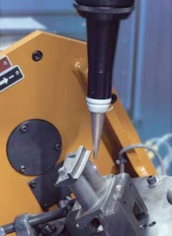
The method that is the subject of this article (and of a U.S. patent application) uses a video camera as its sensing device. This camera, a standard part of a typical laser drilling system, is mounted such that it views the area being drilled through a path coaxial with the drilling laser beam (see Figure 1).
In addition, the method uses both commercially available and proprietary electronic and mechanical components for conditioning radiated light from the laser drilling process and for processing the video signals. The video camera signal is fed into the breakthrough detection processor to compare the level of the signal to a predetermined value corresponding to the onset of breakthrough in drilling. A ‘Breakthrough Detected’ signal is generated and the next phase of the process-to close the shutter, proceed to the next hole location, or continue delivering a user-specified number of additional pulses-is initiated.
SPC Data Acquisition software can be used to log the number of pulses required for breakthrough and to evaluate, in real-time, trends in this parameter. Such data can be useful for detecting contamination of beam delivery components, such as a sacrificial focusing lens cover slide, before this has a detrimental effect on hole quality.
Breakthrough detection is controlled from the CNC drilling program by an M64 command that tells the system to open the shutter and wait for breakthrough detection before executing the next part program block. A typical breakthrough detection command is: M64 N2 X15 E3. The parameters in this line are:
• Nx, where x is the minimum number of pulses delivered. The system always delivers this number of pulses, even if breakthrough is detected before this number has been delivered. The default value is zero.
• Xm, where m is the maximum number of pulses delivered. If breakthrough is not detected after this number of pulses, processing stops and the system displays an error message. This parameter must be greater than zero.
• En, where n is the number of pulses to be delivered after breakthrough has been detected. The default value is no extra pulses. The system delivers n extra pulses after breakthrough has been detected (unless the maximum number, m, is reached first).
To facilitate process development and setup, an oscilloscope card is included in the laser system control as part of the breakthrough detection kit. This card is used to display the camera signal, comparator output, and laser sync pulses that initiate video capture during setup and/or operation.
Experimental results-hole diameter
The effect of breakthrough detection on hole size and airflow consistency was evaluated throughout the development of this method using a standard test piece consisting of pads of 30 holes drilled at 30º from the surface of 1.5-mm-thick Inconel 718 (see Figure 2). Entrance hole diameter is defined as the maximum diameter pin that will fit into the top 25 percent of the hole depth. Exit hole diameter is defined as the maximum diameter of pin gauge that will fit through the entire hole length.
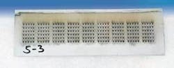
Figure 3(a) shows the distribution of entrance and exit hole diameter produced both with breakthrough detection and using a fixed number of pulses (without breakthrough detection).

The distribution of exit hole diameter shown in Figure 3(b) has been derived from the data presented in Figure 3(a). These curves show that while the mean exit hole diameter for drilling with and without breakthrough detection is the same within 2 percent, the distribution of hole size is significantly narrower when using breakthrough detection.
Consistent airflow
Additional test plates were drilled both with and without the use of breakthrough detection. Plates were drilled with breakthrough detection using from 0 to 3 additional pulses after breakthrough had been detected. Two additional groups of plates were drilled with a fixed number (four and five) pulses. Airflow through each of the pads of 30 holes was measured using a Habco AF100T airflow test bench. Standard deviation of the airflow measurements is summarized in Figure 4.

Two conclusions can be drawn from the data:
1. Additional pulses (two to three) following breakthrough are required to give the most consistent airflow. Back wall damage is minimized when using no additional pulses after breakthrough but this comes at the expense of hole consistency.
2. Use of breakthrough detection with delivery of two or three additional pulses following breakthrough yields more consistent airflow than when a fixed number of pulses is used.
Conclusion
A new method, of breakthrough detection for laser drilling has been demonstrated. The method, which relies on monitoring the visible light radiated from the area being drilled, has been shown to produce more consistent holes as measured by both exit hole diameter and airflow.
References
1. Koegl, Rudolph A. A., Hogle, Richard A., Bauer, Susan D., “Inductive Depth Sensing and Controlling Method and System for Laser Drilling,” United States Patent Number, 5,059,761.
2. Somers, Ralph R., Crow, John M., “Laser Drilling Breakthrough Detector,” United States Patent Number 6,140,604, October 31, 2000.
Terry VanderWert is senior vice president and general manager of Prima North America, Inc. (Champlin, MN; www.prima-na.com).