High-strength steel welding
Laser and hybrid welding present a welding performance increase in terms of productivity and high-quality welds
Frederic Coste, Remy Fabbro, Cyprien Allais, and Jean Paul Mas
Welding of high elastic limit steel, 16-17 mm in thickness, is an industrial application largely performed by conventional welding (automatic GMAW) because of the recognized quality of this welding process, even though it requires a large number of welding passes. For example, GMAW requires five passes at a welding speed of 0.8 m/min for a 12mm thickness plate. Under certain conditions, some constraints on the weld are imposed (no use of back side support for example) and GTAW is needed for the first pass (root pass) with a welding speed reduced to 0.1-0.15 mm/min. The use of several welding stations is one solution to reduce the total welding cycle time, but this is not always possible.
The development of laser sources that deliver up to 4 kW, with optical fiber beam delivery, allows coupling of several sources to get laser power up to 8 kW on the workpiece, making it possible to consider welding of 15-20mm thicknesses in a few passes. The recent development of new laser technology (fiber or disk) that produces powers up to 10 kW, through fibers of a few hundred microns, undoubtedly will advance industrial development of such applications.
The comparison between hybrid processes (GMAW + laser) and laser only (with uses of cold wire) on high elastic limit steel appears relevant. Applications such as welding of large-diameter storage tank or pipe-line prefabrication led us to develop a welding workstation adapted to welding of a large diameter test-tube.
Experimental set-up
The workstation used for this evaluation presents the following characteristics:
An effector oscillates the laser head and the wire or the GMAW torch for welding multi-runs, in order to reduce lack of fusion problems at the interface between metallic pool and base metal. Usually, parts to be welded present an important ovalization that can reach up to one centimeter. This is obviously not compatible with a laser welding or GMAW/hybrid. A seam-tracking sensor SRI (Servo Robot system) controls Y and Z position of the welding head.
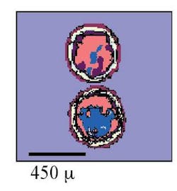
Laser sources used are a HL4006 D (flashlamp-pumped) and a HL4506D (diode-pumped). A TWIN fiber and an adapted focusing system generate two 450-micron diameter spots. Figure 1 shows the intensity distribution, and Figure 2 displays the welding configuration.
null
Due to the low power density obtained with twin spots, the top hat profile, and the Nd:YAG laser power, a specific shape of the joint grove has been designed to optimize the thickness of the root pass, with a correct welding speed.
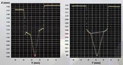
The groove shape for laser and hybrid welding are shown in Figure 3, measured using the SRI system. These shapes allow a welded root pass thickness of about 10 mm, with a welding speed of 0.6 m/min for laser and 0.9 m/min for hybrid welding. For the hybrid process, the V groove is enlarged in order to reduce the risk of open cracks at the top of the root pass.
null
Filling passes strategy
Two filling passes are used to complete the welding of the 4 to 6 mm remaining. Constant parameters (laser power, welding speed, wire feed rate, and beam oscillations) have been used.
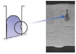
The critical point for filling passes is to avoid lack of fusion on the groove sidewall. Figure 4 presents an example of this defect due to a metallic pool unable to correctly melt the groove sidewalls.
There are a number of solutions for enlarging the metallic pool. Reducing the welding speed can lead to severe drawbacks for use of this process in position welding, and it is not interesting in terms of productivity. By defocusing the laser beam a focus spot of 2 mm diameter is used to enlarge the metallic pool and also to reduce the penetration in the previous pass. Using beam weaving enlarges the metallic pool width (but does not change the length). A combination of the second and third solution is used. Both wire and beam are moved to create a weaving at a frequency of about 8-10 Hz. The amplitude of the beam must be adapted to the groove width.
The geometrical deformation of the cylinder gives, after machining, a significant variation of the thickness to be welded. A typical thickness variation of about one to two millimeters is measured. A filling pass with constant parameters will lead to a flat shape at some places and an important over-thickness in other places. This is not compatible with a correct capping, for which a regular flat surface is needed. The SRI system is used to measure the volume remaining to be filled after the second pass. The volume measurement is used to calculate the corresponding wire speed that is corrected on line, as well as the position of the welding tool inside the groove.
Figure 5 shows an example of the evolution of the wire speed. Lower and upper limits are imposed. A too high wire speed leads to an incorrect melting of the wire (defects) and a too low limit could lead to a discontinuous process, with possible stops of the wire, which could also create defects at the restart of the wire, and potentially a destruction of the wire by excessive heating.
null
Hybrid welding
The goal of hybrid welding is to increase the performance obtained with the laser alone, mainly in terms of productivity, with a constant quality. Laser parameters are kept identical as those used with cold wire. The hybrid process necessitates setting parameters more so than the conventional one.
- Wire speed: The upper limit of this parameter to guarantee a correct melting with cold wire is about 10 m/min, the laser has to melt the wire. With GMAW, the wire is melted by the electric arc and wire speed can be increased, up to 19 m/min.
- Laser beam position: with cold wire, the wire has to cross the laser beam to be melted. Using GMAW, the laser is used to make a longer pool and manages the metallic pool created by GMAW process. The distance between arc and laser has to be optimized.
- If using GMAW in a narrow groove, the arc shape has to be controlled in order to minimize the effect on the groove edge. Different operation modes can be used, like pulsed or continuous mode.
Root welding speed is increased up to 0.9 m/min, laser power is kept constant and a wire speed of 10.5 m/min, and pulse mode is used for GMAW.
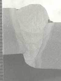
Gaps between parts are well controlled but the tube ovalization can generate a rather important mismatch. On some test parts, mismatch varies from 0 to 5 mm. Welding with constant parameters (same welding speed, wire speed, GMAW parameters) is tested on such a variable configuration and gives interesting results (see Figures 6 and 7).
null
null
Filling passes strategy
Concerning the filling passes, two modifications are done compared to the laser alone.
- The wire speed is increased up to 17 m/min.
- The width of the arc is important and corresponds to the width of the groove. So the torch is fixed and only the laser beam is weaving. This allows a better melting of the groove wall by the laser, but without the risk of creating a cavity with the arc.
The laser parameters are the same as those used for cold wire but welding speed is 0.9 m/min. Three filling passes are needed to obtain a complete seam up to the surface and capping is achieved with two passes. One is shifted on the left, with a wire speed 17 m/min, and a second one is shifted on the right with a wire speed reduced to 10 m/min. In both cases, the welding speed is 0.9 m/min. The advantage is the total suppression of an undercut and a very smooth connection between the base metal surface and the weld itself.
Metallurgical results
The weld is tested by radiography. No defects are detectable, no pores, cracks or lack of fusion on laser alone welded seams. We have observed some small pores on hybrid-welded seams, but their number remains acceptable. Hardness profiles give a maximum value of 330 HV at the bottom of the weld (with an important proportion of base material), but this is compatible with construction code. We have to consider that the base material (high strength steel) has a hardness higher than with standard steel.
The measured resilience gives very interesting results, with energy absorbed up to 110 J at a -10° C temperature with laser alone, and up to 220 J with the hybrid process at a temperature of -10° C, probably due to the higher welding speed.
Conclusion
Interest of laser and laser + GMAW processes compared to the conventional GMAW is demonstrated. The table summarizes the main parameters in order to achieve welding of a thickness of about 17 mm with these processes.
| GMAW | Laser | Laser+GMAW | |
|---|---|---|---|
| Welding speed (m/min) | 0.4-0.6 | 0.6 | 0.9 |
| Number of passes | 6-8 | 5 | 5-6 |
| Resilience (J) | 80 | 120 | 220 |
Laser and hybrid welding present a welding performance increase in terms of productivity (reduction of the number of passes and an increase of the welding speed). Moreover, the mechanical properties of the welded zone present higher quality compared to conventional welding. Such results are encouraging for a potential use of these processes for production. The recent development of new laser technology, with the increase of power density, will allow an improvement of the actual performance, and will easily facilitate the industrialization of this process by a size reduction of the laser and the tools.
Frederic Coste and Remy Fabbro are with Laboratoire pour l’Application des Lasers de Puissance, Arcueil, France. Cyprien Allais and Jean Paul Mas are with SAIPEM-SA., Montigny le Bretonneux, France


