Let the chips fall
Laser assisted chip control is a novel laser application whose time may have come
Edward Rutkowski and Thomas Kugler
Lasers have been employed in almost all areas of metal processing-cutting, welding, heat treating, brazing, cladding, marking, and forming-but not machining and turning. Turning metal parts and machining with cutting tools is a very old process. Countless innovations in the systems and process have been made but there is still one nagging issue: chip control. Quality, safety, cycle time, and cost can be improved when chip-related issues are solved. The long chips that are produced during the turning process, especially with low-carbon steels, create many problems and extra costs.
Chip-related problems
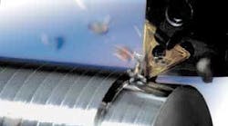
A tool insert in a turning center’s tool holder removes material by peeling it up and away from the base metal (see Figure 1). As the chips form and are pushed down onto the part ahead of the insert they will break in zones of local damage that lose strength, kink, and ultimately fail. In order to break, the chip must have experienced stresses from contact with the workpiece that exceeds the maximum tensile fracture level of the chip. Controlling chips means breaking the chips and keeping them in small tight spring-like curls rather than loose bird’s-nest bundles.
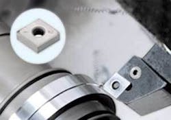
In theory, chips can be broken during the machining process itself using chip breaker inserts (see Figure 2). These inserts have special geometry that bends the chip causing damage and breaking it. Chip breakers, however, work best at a certain surface feed rate and depth of cut and these cannot be held constant due to changing cut geometries and tool wear. Finish passes, where the cutting depth is much less, are more ductile and prone to chip problems because their metallurgy makes them much less prone to chip fracture from embrittlement.
null
Chips that don’t break create havoc inside a machining center by wrapping themselves around the part or tooling that can gouge the workpiece creating scrap and/or reduce the life of the tool insert. Chips can hang-up on spindles, fixtures, inserts, gauges, and automation. Many machining applications where automating gauging is to be used to improve tolerances must abandon the practice when chip problems foul up the gauges. Similar chip fouling problems plague automatic load/unload equipment intended to improve the economics of high-throughput machining systems.
Coolant to flush the chips from the workpiece and prevent them from getting wrapped around it or the tooling is another chip control method. Used as a lubricant with low-carbon steels, it is supposed to prevent welding of the chips to the tool or workpiece and lessen any built-up edge on the insert. Coolants, messy and expensive, are also a potential health hazard, reduce the scrap value of the chips, and their disposal adds more cost.
Screens, conveyors, filters, hydro cyclones, and centrifuges to remove metal chips and fines from the coolant are necessary. Skimmers, settling tanks, and coalescers are needed to remove tramp oils. Bacteria prevention employs the use of aeration, sump hygiene, sump cleaning, and biocides. Coolants can cause dermatitis in workers who come in contact with the fluids and the risk of disease from bacteria in the fluid is serious. The cost of coolant was considered to be 3 percent of the cost of a machined part in the 1980s. Now that cost can be as high as 16 percent.
For high-volume machining operations chips must be moved from the machining center to a hopper for recycling or disposal. This usually involves some kind of chip conveyor in a trench. Large masses of unbroken chips easily become entangled in these conveyors requiring manual clearing, which is time consuming and dangerous. Accidents with razor-sharp chips are common. Small chips require less volume, estimated at one-tenth that of large spiraling chips, so poor chip control greatly increases the storage and shipping cost. Also, chips soaked with coolant are worth much less as scrap metal than clean, dry chips. To get value from their chips, machining facilities have chopping and drying systems on site. In general, coolant-contaminated chips are removed by reclamation vendors at no charge but with no payment for metal value.
Increasing throughput
Throughput is the key to cost savings in machining, and the main loss of potential throughput is due to poor chip control. Automation of the machining process requires consistency in the process and the parts. Robot unloading of a machining cell is problematic if chips are fouling the part because grippers cannot securely hold a part wrapped in chips or if long chips are snagged on the tooling and spindle.
Quick-change tooling is another automation-boosting method. When a tool insert is near the end of its life the tool holder and insert are changed automatically as a quick-change tooling set. The new tool is preset in the correct position and machining continues without any scrap test parts or the time needed to make manual tool changes and recalibrating the tool position. However, quick-change tooling is expensive and large chips can foul the tool, damaging it and forcing the user to revert back to standard low-cost “stick” tooling.
Tool insert costs in a machining program are not very high, perhaps 3-5 percent of the job. Unpredictable tool wear and broken tools add the real cost. This requires the downtime of a manual tool change and the scrap parts that are run to re-qualify the machine. Chip control problems are almost always the cause of unpredictable tool wear due to dragging and snagging chips. Once chip control is a reality, tool life becomes predictable and automatic quick-change tooling can be used economically.
An example from an automotive machining operation of forgings illustrates this scenario. A large automotive component manufacturer purchased three machining centers installed around a single robot for automated part load and un-load, and the machines were equipped with automatic gauging for real-time tolerance control. Meant to produce 500 parts per shift, chip control issues made both the robotic manipulation of the parts and the automatic gauging impossible. Two operators for each of the three machining centers replaced the automation in part load/unload and also had to manually clear chips from the machines. When Laser Assisted Chip Control (LACC) was applied to the raw forgings in a test run, these three systems could, once again, employ the robot and automatic gauging and the throughput was increased to 1,500 parts per shift creating a 67 percent reduction in per-part costs from throughput increase alone.
Laser-Assisted Chip Control
Using a laser to scribe the surface of the part to just above the finish diameter creates an engineered interrupted cut when machining the part. The scribe is narrow and the depth easily adjusted by control of laser parameters and speed.
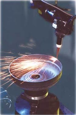
The laser scribing process is simple. A laser beam is focused onto the workpiece along with a coaxial jet of air or oxygen. Laser energy is absorbed by the metal and vaporized and melted metal is blown out of the scribe by the coaxial jet. Low average laser powers and high speeds are used for shallow scribes while higher energies and slower speeds work for deep scribes. In most cases the laser beam is moved relative to the part, so a robot with a fiber-delivered laser focus head is employed. Deep scribes in the 3-6mm range or alloys prone to hardening are best produced by a pulsed Nd:YAG laser. For mild steels and scribes below 3mm depth a Super Modulated CW Nd:YAG laser produces the most throughput at the lowest cost. In general, these lasers have an operating cost of less than $6/hour and can usually scribe a component in less time than machining cycle.
The component is fixtured as it would be in the machining center. The robot moves to the start of the first scribe location and the laser system ramps up to the pre-set laser parameters. A capacitive height-sensing focus head, the same used for robotic laser cutting, moves down into position and the coaxial gas solenoid valve is opened under robot control. Next the laser shutter opens as the robot begins moving to make the scribe. Any changes in speed or laser settings are controlled by the robot controller. Scribes can be made in one place on a part, on three or four sides, and even small short scribes can be made for a deep notch area. If multiple scribes are used the angular separation of the scribes is slightly asymmetrical to eliminate the chance for resonance.
Laser scribes are narrow, generally on the order of 0.25 mm. This creates a very short amount of time and distance for the interrupted cut by the tool insert but enough for total chip control. Scribing speeds are dependent upon the depth of scribe and the laser employed. Figure 3 illustrates typical scribing speeds for pulsed and super-modulated CW Nd:YAG lasers.
Adding laser scribe lines to the raw part can virtually eliminate all the problems related to chips, chip conveyance, and coolants. The narrow scribe line momentarily interrupts the cut of the tool insert creating a short chip that easily flies away from the cutting area. The number and position of the scribes is engineered to control the chip. Because chip control is no longer a problem at any surface speed, the process can be optimized to have the chip itself take the heat of machining away allowing fewer machining passes. Dry machining, and the use of lower-cost inserts or wiper inserts, produces a better surface finish, even in low-carbon steels.
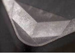
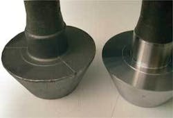
Figure 4 shows an 8625H alloy stem pinion for an automotive axle with a laser scribe depth that varies from 0.005 in. to 0.026 in. One scribe might be sufficient at the smaller diameter areas but two or three scribes are best for the larger diameter beveled section.
The 1010 stamped torque converter bowl for an automatic transmission shown in Figure 5 uses three scribes on the thrust face that are about 0.018 in. deep and 0.075 in. deep scribes on the rim of the bowl. The thrust face surface finish is critical to operation and chip-related defects were a problem.
Courtesy: Cutting Tool Engineering
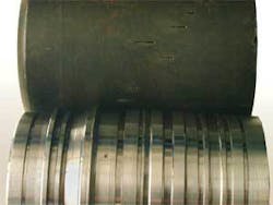
Perhaps the most complex part for LACC is an intermediate hub (see Figure 6) for an automotive transmission where many deep narrow machined grooves are required. Laser scribes in this part were made with a pulsed Nd:YAG, creating scribes from 0.8mm to 6.5mm. Many stops and starts are required and the laser parameters are changed for each.
A new machining paradigm?
By adding a low-cost, fast, pre-machining process some big benefits can be achieved with conventional machining, automation, and gauging equipment. Higher throughput and less downtime result due to predictable tool life. Higher yields are achieved due to the elimination of chip-related scrap. Dependable automation with no chip-related fouling and automatic gauging without interference can be accomplished with fewer machining passes to save time and money.
Lower-cost inserts with longer life and wiper inserts for better surface finish can be used. Dry machining for lower cost and no health/environmental hazard are a plus. Simpler chip conveyance, storage, and trucking are experienced and recycled chips have higher value
Cost savings calculations are difficult due to the fact that the benefits are based on specific part geometries, scrap rates, and cycle times. Some part-specific paybacks analyzed for automotive forgings have shown a potential for up to 60 percent lower costs and 70 percent less cycle time compared to present machining practices.
References
1. Marusich, Thiele, and Brand, Simulation and Analysis of Chip Breakage in Turning Processes, 28 Mar-01.
2. Minnesota Technical Assistance Program FACT SHEET: Developing a Coolant Maintenance Program for Machining Operations, 12/96-63.
3. Graham, Huddle, and McNamara, “Machining Dry is Worth a Try,” Gardner Publications Inc., Modern Machine Shop, MMS Online.
4. “Metal Cutting Physics,” MIT On-Line Instruction.
5. Kennedy, “Let the Chips Fall…”, Cutting Tool Engineering, CTE Publications Inc., October 2002.
Ed Rutkowski ([email protected]) is COO/director of engineering for Americhip International Inc., Plymouth Township, MI. Tom Kugler ([email protected]) is the applications engineering manager for GSI Group Laser Division, Novi, MI.
