Evaluating blank edges
In the tailored blank welding process, the condition of punched and cut edges of steel blanks is of decisive importance for subsequent laser-welding processes. A three-dimensional edge-inspection device that enables quick evaluation of the produced edge and makes it possible to reduce the maintenance and set up times for punching machines is available from Voest-Alpine Mechatronics GmbH (Linz, Austria). The measurement reports produced by the KIG3D system enable optimized pairing of the blanks to be connected, forming smaller and more constant welding gaps. This leads to a substantial reduction of rejected components.
Industrial implementation
null
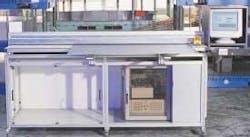
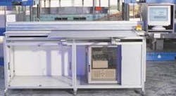
The KIG3D is a compact, standalone measurement table that is preferably set up directly adjacent to the production plant (see Figure 1). The dimensions of the measurement table are a result of the customer-specific parameters related to the size of the blanks to be measured. A typical system design allows the measurement of blanks with edge lengths of up to 2000 mm and thickness ranging from 0.5 to 10 mm.
Theory
null
Figure 2 shows a model of the cut edge, which is the basis of this method of measurement. The dimension of zones C, B, Bu and D are characterized most importantly by material properties such as tensile strength, yield strength, hardening and so on. The angles at which these zones present themselves are primarily effects of the configurations of the cutting tools (such as cutting gap) and the arrangement of the hold-down clamps.1,2,3 The breaking zone is a surface that results from the separation of the material in the structural area of the metal. Its thickness is thus subject to statistical fluctuations.
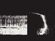
The measurement principle is based on the light sectioning method.4 The three-dimensional data of the form of the edge lies in the inspection of the diffuse reflection of a line projected onto the edge at a flat angle. The extraction of the form of the line from shots whose quality is determined by the smallness of the object of measurement as well as by the erratic deformation and separation in the structural area is a special challenge for a measurement system. Multi-stage intelligent image-processing algorithms are used to reliably ascertain the desired measurement values (see Fig. 3).
null
The straightness of the edge, among other things, is the effect of the cutting tool configuration in longitudinal direction. Discontinuous edge abutment, angle offsets and so on affect the straightness of the edge, which in turn directly affects the welding gap. Methods that use a constant welding gap (such as hold-down rolling) are effective only in a very limited range in the event of edges that are not straight.
Edge straightness is determined by means of a high-precision linear drive that guides the light sensor along the entire edge of the strip. In addition to determining straightness, the sensor also supplies a large number of measurement results pertaining to the shape of the edge, shape changes during the course of one cutting tool block and from one cutting tool block to another. This is a pronounced advantage when compared with expensive micrographic methods. Unsure measurements resulting from local characteristics such as structural inconsistencies are reduced. By taking the mean of several shots of a small section, the quality of the measurement can be improved by reducing the statistical fluctuations.
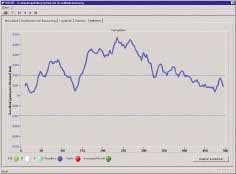
The sum of the shots taken is used to create a three-dimensional topographical representation of the cut edge. In the next step this results in obtaining the parameters that are typical for this process as well as their changes along the entire length and representing these data in a graph. The cut angle β, the breaking angle α, the relationship of the cut zone to the breaking zone C/(B+Bu)6 and the straightness shown in Figure 4 are represented.
null
Using this method cut angles are determined with a preciseness of at least ±0.5 degrees. Dual-edge straightness is determined at a preciseness of better than ±0.02 mm.
In addition to the measurement of the entire edge in one measuring step, a random section of the edge of nearly any length also can be measured, no matter how small. This makes it possible to zero in on critical areas such as cutting tool breakouts, defective abutments and so on. The measurement capacity test for quality assurance is performed by means of a calibration sheet that is part of the scope delivery.
Summary
Because the automated welding process can have only a limited effect on the welding gap, it is absolutely necessary to have a high-quality edge in order to guarantee excellent welding results. No matter how "high tech" the welding process, a good basic raw material remains essential. The KIG3D system substantially contributes to the minimization of rejected tailored blanks during the welding of punched edges. This contribution is a direct result of being able to determine the cut and breaking parameters simultaneously with the straightness of the edge. Precisely measuring blanks makes it possible within a matter of minutes to determine cutting tool quality during punching. Furthermore, the regular measurement of punched blanks makes it possible to inspect changes in the condition of the tool and thus the service life of the tools can be better utilized through long-term observation. This method of measurement can also be used for milled or trimmed edges. The measurement of edges of other materials such as plastics is also possible.
References
- Schmütsch H. H., Fertigungstechnik Nr. 196, VDI Reihe 2, (1990).
- Schnittflächenqualität beim Schneiden, Beschneiden und Lochen von Werkstücken aus Metall, VDI Richtlinie, (Mai 1994).
- Reinertson, J.R., Iron Age 11, p. 55–59, (1951).
- Ofner, R., Three-Dimensional Measurement via Light Sectioning Method, Dissertation, Montanuniversität Leoben, (April 2000).
- Hlobil, H., Reisinger, J., Georgi, R., Müllner, A., O'Leary, P., Leitner, M., Visualisierung und On-line-Dokumentation der Schweißnahtvorbereitung bzw. des Kantenzustandes, DVS-Berichteband 209, Verlag für Schweißen und verwandte Verfahren DVS-Verlag GmbH, Düsseldorf, (2000).
- Reisinger, J., Kogler, A., Georgi, R., Schickmaier, W., Development and use of an edge inspection system on cold rolled products, 2000 AISE Annual Convention, Chicago, Ill., Proceedings, 09/2000.
Helmut Hlobil is coordinator of Optical Measuring Systems and Johann Reisinger is head of Measurement System Development with Voest-Alpine Mechatronics GmbH, Voest-Alpine Str. 3, A-4031 Linz, Austria.


