Clean laser machining
When you look at a laser cut under a microscope, you see a nice cut. But you also may see a heat-affected zone, slag, recast, re-deposited molten debris and oxidation.
A sacrificial layer of material and use of a secondary process to remove the sacrificial layer may be required to improve quality. Other approaches use chemical etching, plasma etching or other processes to clean up the laser-treated material. These secondary steps tend to be too expensive or impractical to be put into production.
Some promising techniques have resulted in cleanly etched features. A process patented by Gupta et al.1 of IBM has the material completely immersed in a liquid bath. The majority of current applications would not accommodate this level of complexity and cost. Professor Geiger and his group at the University of Erlangen-Nuremberg, Germany,2 were closer to solving the problem, but fell a bit short of optimization. References abound for other processes that simply use capillary action from placing liquid under a transparent optical material in close proximity to the part being machined. The problems associated with these techniques are obvious: improper or too deep a liquid level for any reasonable pulsing of the laser except at very low repetition rates. Anything but a thin film (significantly less than 1mm thick) creates bubbles from excessive sonic cavitation when higher energy densities are used, and therefore deleterious refraction effects will dominate the process and create rough features. As a consequence it is too expensive or impractical to incorporate such methods into an industrial setting.
An innovative, patent-pending process offers promise for reaching engineers' expectations for lasers to solve their machining problems. The technique is called Clean Lase, an acronym formed from Cavitated Liquid Etching Assist iNnovative LASEr machining.
The simple process works with any laser type, as long as the liquid being used as the assist is not strongly absorbed by the laser in use. It works particularly well with a pulsed ultraviolet laser. A spray nozzle atomizes the liquid onto the laser interaction zone so that a thin, laminar flow of liquid blankets the laser interaction region. This liquid completely removes the presence of oxygen (a primary catalyst of unwanted debris) and provides a barrier between an oxygen environment and the material being machined. Plasma is greatly reduced and more energy can now be efficiently coupled into the material. The laser energy now coupled into the material begins to melt and vaporize the exposed region. Localized sonic cavitation takes place and micro-bubbles begin to implode during the lasing process, ejecting the molten material from the machined area. The liquid blanket sweeps away the solidified, molten droplets from the laser-machined area leaving a feature with no slag or debris buildup. The strong agitation of the sonic cavitation also prevents burr or recast formation on the edges of the exposed area. What is left is a close-to-perfect cut.
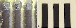
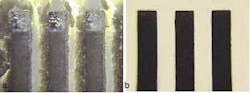
All materials tested to date have benefited from the Clean Lase technique. Figure 1 shows two pieces of silicon etched by a KrF excimer under air and liquid assist. The sample in Figure 1a has an extensive buildup of slag and debris. The sample in Figure 1b, processed with a liquid assist, exhibits clean and debris-free cuts—with no post processing. Not only did the liquid assist produce a cleaner cut, but also the time to cut through the material decreased by more than a factor of three.
In another case a Nd:YAG laser was used to cut 670µm-thick silicon (3 watts of power @ 355 nm, 15 nsec pulses, 10 kHz repetition rate). The fastest cutting speed of the silicon without the Clean Lase process was ~8 mm/.minute. In contrast, the speed increased to >20 mm/minute with the Clean Lase technique, nearly a three-times improvement.
A 248nm excimer laser processed a stainless-steel sample under identical laser conditions: 6 J/cm2, 200 µm × 200 µm spot scanned linearly with 20 pulses per unit area. The depth of each slot for the unassisted case was ~9 µm and then increased to a depth of 37 µm with the liquid assist. Close inspection of the samples showed that in the unassisted sample there is a large debris field of oxidized material and the edges of the feature have significant recast and burr formation (extending in excess of 42 µm above the surface). On the other hand, the liquid-assist treated sample shows no indication of oxidation, recast or burr.
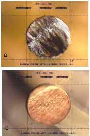
Figure 2 shows two 160µm diameter beryllium copper pins cut using a 355nm Nd:YAG laser. The pin in Figure 2a exhibits significant slag and oxidation, whereas the pin in Figure 2b shows an oxide-free, burr-free cut.
The Clean Lase process even works on three-dimensional surfaces. A frequency-tripled Nd:YAG laser machined a spiral cut in a 0.5mm outer diameter and 0.25mm inner diameter stainless-steel tube. The width of each spiral turn was ~56µm wide and the total length of the spiral was > 2 mm.
This part almost looks as though it were cut on a screw machine. Previously, it was not possible to make this part without the use of the Clean Lase process.
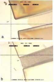
The Clean Lase process also works on polymers. Figure 3a shows a thin polymer film used as an optical waveguide that has been etched with a 248nm excimer laser and a blanket of helium gas over the laser interaction region. Helium is a common choice of assist gas for ultraviolet laser processing. Yet even with the helium cover gas, the debris (mostly carbon) generated is still excessive and undesirable, not to mention that the fine features are not resolved and are for the most part simply etched away. The micrograph in Figure 3b shows the same material etched under identical laser parameters but with the Clean Lase process applied. The features in the sample in Figure 3b are resolved to better than 2 microns. The difference between the two photos is clear. Not only is the soot reduced, but the optical resolution has been enhanced as well. The Clean Lase process further reduces the heat-affected zone that would otherwise add to the distortion of the edge of the feature.
References
- A. Gupta et al., United States Patent Number: 5,057,184 (1991).
- S. Roth and M. Geiger, Specific Surface Treatment by Laser Irradiation Under Liquid Films, ICALEO 2000.
Michael Scaggs is executive director with Neoteric Concepts LLC, Weston, FL. Contact him by e-mail at [email protected].