Tubular attraction
Those who use tube or profiles (collectively 'tube' here) derive substantial benefit from the exploitation of these versatile materials. Unfortunately, many designers fail to think 'tube' as a potential raw material so their product can lose out on a substantial competitive advantage.
Some industry sectors—including furniture, leisure equipment, hospital equipment and increasingly the auto industry—have used tube as a structural material for many years. However, a product does not have to be made in large volume for tube use to be beneficial; laser processing adds the advantages of practical, reliable production of small batches and precise versatile production. Further, parts are produced with very low waste.
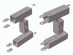
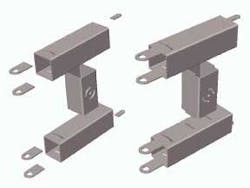
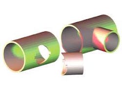
Tube's attractions include its easy availability in a wide range of sizes, shapes, materials and finishes. It has a high section modulus for its weight and low cost for its strength. Laser-cut tube can result in the elimination of multiple processes (see Figure 1) with consequent cost and cycle time reduction and quality enhancement. Particularly exciting are those cases where creative design eliminates the need for jigs and fixtures.
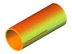
Seamed tube is joined (see Figure 2) by a wide variety of welding and brazing technologies, including CO2, Nd:YAG and direct-diode lasers. The laser welding head is integrated with the final stage of the tube-forming mill, where strip is closed to form the tube. The benefits are improved process consistency and mill versatility.
Cutting to length and bending are the most common processes. While there are currently no production bending applications for lasers, they are used occasionally for straightening tubular parts in demanding applications.
Cutting to length is usually economic only when the laser machine is processing other areas of the part, the required cut is not straight, or special considerations apply, for example very thin wall or very hard material. The balance moves in the laser's favor through cut quality, freedom from burrs, speed and precision.
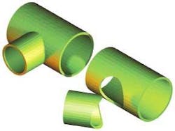
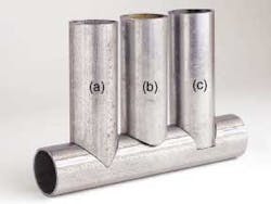
Lasers have a potential role whenever tubes are to be joined together, first in cutting the tubes to fit and then in welding them. The more precisely they fit before joining, the more successful will be the joint. The more complex the joint, the greater is the case for using lasers; the opportunity to eliminate the cost and weight of fittings is a key advantage. The snag is that good fit implies complexity. The saddle joint of Figure 3 is an improvement over conventional welding joints at the expense of complexity, whether the branch abuts the main tube or inserts into it. It still has the disadvantage that tooling is required to locate the parts during joining. This reduces access and becomes annoying if a variety of joint angles is required, as in custom cycle manufacture.
Features that eliminate the need for tooling are attractive; for example, the form shown in Figure 4 may be modified to make the branch lock into the larger tube. When the branch is the same diameter as the main tube, a neater solution is shown in Figure 5a. This too may be modified to permit the parts to be locked together. Once the parts are cut to fit well, welding, brazing or adhesive bonding will complete the joint. Another attractive form is shown in Figure 5c. When this serves a purely mechanical purpose, the branch may be cut off square. Where flow is required, it is shaped to the bore of the main pipe.
The geometry becomes more complex with intersections at other than 90 degrees, or when the axes do not intersect. However, this is not a problem with suitable CNC machines. The low force of laser cutting is a key benefit for thin tubes.
The system
Tube cutting systems vary widely from the addition of a rotary stage to an X-Y machine to systems of great sophistication. Additional to the laser, beam delivery, motion systems and safety enclosure, complete systems may include automatic or manual loading and/or unloading, tooling to cope with non-circular tubes and profiles, means to locate a seam, assist gas nozzle, automatic height control, steadies for long parts, a live tailstock, multiple cutting heads, fume extraction, automatic swarf removal, means to prevent back-wall damage, gauging to locate tube or profile features and tube structure design CAD. Machines can cope with tube up to 0.5 m diameter or up to 8 m long, and may have from two to five axes.
As there is considerable variety in the capability and implementation of 'standard' systems, and seemingly endless possibilities for custom systems, it is most important to define the spectrum of work that you wish to undertake before investigating the range of machines on the market. A critical decision is whether you need a dedicated tube-cutting machine or a tube cutting capability on a flatbed cutter or five-axis cutting machine.
Cutting-only machines are generally based on a 'conventional' architecture of linear and rotary axes, with great variety in how these axes are distributed between moving the work and moving the focus. Tube welding systems, and those that weld and cut, may use articulated arm robots. Robot-based systems may move either the work or the focus with the robot. The systems that are used to weld complex tubular frameworks are usually based on one or more robots.
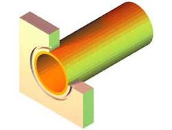
Tube-to-tube plate welding (see Figure 6) with a laser is little different from the use of arc processes. There is some variety in the approach taken to deliver the beam and manipulate the focus. For large boilers and heat exchangers, it is common to use a robot to manipulate the beam, which is delivered either by optical fiber from a Nd:YAG laser or by a flexible beam guide from a CO2 laser. Smaller assemblies may be made using a three- or five-axis machine, the work being taken to the laser. The robot effectors often take the tube bore as a mechanical reference. Copper shell and tube heat exchangers use plunged holes in the tube plate to yield a geometry more convenient for laser welding; this also provides an interference fit.
A specialized application concerns in-situ repair of worn or corroded pipework by the insertion of sleeves. An effector is inserted into the tube bore and works from the inside outwards to make the weld. Usually a Nd:YAG laser and fiber-optic beam delivery are used but CO2 systems have been employed. One common application is the repair of nuclear reactor steam generators. The laser with its control and services are installed in a trailer, from which the beam delivery is unrolled rather like a fire hose.
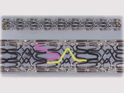
An intriguing small-scale application is the manufacture of stents, either by cutting from tube or by welding from wire or tubular components (see Figure 7). Stents are scaffolding used to hold open blood or other vessels. They are collapsed for insertion by catheter and then open up when they are in place. Their diameter can be from a fraction of a millimeter upwards. Stents are made in a wide range of designs to meet the specific needs of the application and of the surgeon installing them. Their manufacture has stimulated the development of machines and processes that are applied to the manufacture of other products from fine tube, for example small filter screens.
Design freedom
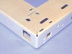
Manufacture from tube is ancient, and mechanical and arc processes have developed to support it. So too have clever designs that have proven convenient and reliable. An example is shown in Figure 8, part of a 1970s dishwasher. Produced mechanically, this does not have the precision of laser-processed parts but it illustrates several useful features: circular notches at the ends of the bend line help to locate the bend and avoid the need for an accurate profile at the end of the miter, though the latter is no problem with many laser machines. This is achieved without introducing a severe stress raiser that might lead to a fatigue problem.
The departure from a regular miter cut allows holes for fasteners to be placed on the miter line.
The neat fold-tab fixing secures the bend. and can be used alone or to hold the assembly for subsequent joining processes.
Design aids
Designing the intersection of tubes, even using a general-purpose CAD system, is not easy but is made simpler by the capable CNCs fitted to tube cutting machines. However, it does become easier when using one of the special-purpose tube CAD systems now available. These vary from simple systems that 'wrap' a 2D CAD drawing around the tube. Some allow the designer to position the tube axes and define the tube profiles; they then compute the required cut geometry and pass the result to the post-processor to produce the CNC program for the cutter. The selection of a suitable CAD or CAD/CAM system is an essential part of the specification process, to achieve the best from a machine investment.
Comment
This article is a sequel to one published in June 2002 in The Industrial Laser User, magazine of the Association of Industrial Laser Users (AILU). The author is indebted to the members of AILU who made comments and suggestions, and to those who allowed him to use photographs or to photograph their products.
Tim Weedon, a consultant and the current president of the AILU, can be contacted by email at [email protected] or by phone at +44 1788 560960.
