DOEs and HOEs for microwelding
Many of today's laser microwelding processes involve use of the multiplexed or splitter-based beam sharing optics. Once split, each laser beam is delivered to the targeted weld areas by a fiber beam delivery system with an attached monolithic refractive optical focusing head.
Fiber beam delivery is employed in coarse to medium precision applications where the ultimate alignment of the two elements being welded is not absolutely critical. However, in certain automotive welding applications, such as High Intensity Discharge (HID) lamp alignment and welding, a lack of precision can lead to non-conformance yield loss and premature failure of the lamp once it is installed. The balancing of laser energy through coated splitters with the subtle time delays caused by transferring laser energy through differing lengths of fibers creates weld variations and directly affects the performance of the HID lamp.
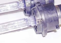
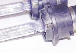
Figure 1 shows a typical spot-welded tab; there are three such tabs on the bulb assembly near the base. The position of the discharge illumination centroid with respect to automotive head light housings is absolutely critical, as are both the simultaneous welding of the tabs and the quality of those welds. Because these bulbs create a discharge by using high voltage to initiate the arc, a poor weld will cause arcing at the tab and eventual failure.
In other critical applications, such as welding lids on electronic packaging to form a hermetic seal or spot welding optical components into position, these subtle laser energy variations create specific adverse effects, such as part deformation and misalignments. These are common traits of the existing fiber beam delivery processes. Engineers have developed methods for overcoming or compensating these obstacles by adding further vision analysis, process time and spot welding sequences that allow corrections to take place as parts are being welded. The drawback of these added process steps is a serious reduction in throughput, and in high-volume manufacturing. In the worst-case scenario, process engineers add mechanical deformation motion techniques to the pick-and-place robotics to mechanically tweak the parts after the welds are made.
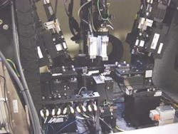
Applications employing fiber delivery often present uneven beam intensities that create two major problems. First, overlapping and uneven weld zones create undesired weld variations. Second, there is an inability to control the balance between the fiberoptics with the precision necessary to ensure sub-micron alignment repeatability in a single process step. Typically, each fiber will have different optical losses, and precise balancing is only achieved by adjusting attenuators and/or the focusing optics to maintain specific on-target laser intensities. Either way, the issue is one of achieving balanced welding characteristics so that all the resulting welds have similar properties. Also, no weld should effect the mechanical positioning of the precision aligned assemblies that are being welded; however, it is clear that this is a difficult task under any circumstances. Figure 2 is an example of a typical fiber beam delivery-based welding system for the telecom market.
Understanding the dilemma faced by industry, a new technological solution has been developed. A processing head can be configured to fit onto the end of a single fiber-optical delivery system using diffractive and holographic optics (see Figure 3). This new optical beam shaping, splitting and focusing head provides a greater degree of precision welding for applications in telecom devices, lighting fixtures and hermetically sealed electronic packages. This new technique takes into account the need for illuminating a variety of points or surface areas with balanced laser energy by simplifying the optical system through elimination of the use of splitting and launching the split beams into fibers. Diffractive and holographic optics provide further advantages for applications such as optimizing laser illumination beam shape, laser micro-level spot welding, seam welding, plastic welding/bonding and area surface exposure of photo or thermal cured materials. By allowing precision to be designed into the optic, the process precision is increased substantially.
The optics used for microwelding and bonding applications can be simply classified as either diffractive or refractive. Refractive designs consist of large-scale surface relief profiles designed using the laws of geometric optics, i.e. large curvatures. They treat light by the refraction and reflection of geometrical rays at optical interfaces. With geometric optics, a wider variety of wavelengths can be used with refractive designs as long as the material can transmit the specific wavelength being utilized.
Diffractive optics consist of planar elements with zones that retard the incident wave of light by modulating the refractive index, or in the case of surface structures, by modulating the surface profile. The light emitted from the different zones interferes and forms the desired wavefront profile, which can consist of a specific shape or an array of spots. The key limitation to diffractive optics is their dependence upon interference, making them wavelength-specific optical elements; one design cannot be used efficiently over several wavelengths. They are, therefore, limited to monochromatic applications.
Diffractive and holographic optics are designed to provide unique and various beam pattern shapes for multi-spot, stitch-and-seam micro-weld, or bonding applications. Other laser beam shapes include circular and rectangular zones that cover an area or circular and rectangular arrays of individual beam focal points or geometric spots.
Generated by computer software, diffractive and holographic optics are, by default, versatile when it comes to the design of elements with specific attributes. A diffractive optic can assume a specific beam profile, such as those shown in Figure 4. Each profile offers certain microweld characteristics, such as large spot welds, small tack welds or even deep penetrating welds. In the case of bonding, photo-curing adhesives or photo-initiated bonding of polymer pre-forms, optimized shaped illumination of diode laser beams offers a higher degree of control of heat flux on targeted areas, instead of flood approaches that are traditionally used.
When multiple and simultaneous microwelds are required, a diffractive optic splitter coupled with a diffractive imaging element can provide superior control of the spot-to-spot beam fluctuations that commonly occur while using fiber-based splitting beam delivery. Diffractive and holographic optics can provide a smaller beam delivery footprint in comparison to multiple fiber-based delivery systems. When aligning multiple micro-sized optical components, the compactness of the optical system can provide added room for further vision or more robust material handling.
Another key feature is the ability to simplify stitch-and-seam welding of lids or other polymer or adhesive sealing of hermetic enclosures or silicon MEMs packaging. Figure 5 shows a scanning system that provides seam welds or bonds using cost-effective motion control instead of expensive galvanometer scanning routines. Configuring the optical imaging head with indexing optical elements, a system can quickly change spot patterns or beam energy densities on the target. These added capabilities make changes possible on the fly, providing further flexibility to an overall precision assembly process.
Diffractive and holographic optics present many advantages, although initial investment can be significantly higher than traditional refractive optics. That said, once produced, they can be replicated at fractions of the cost of their refractive counterparts and ultimately their return on investment (ROI) far exceeds those initial costs due to increases in process yield and throughput. This should not discourage those who need to solve problems such as laser beam delivery footprint issues, spot size limitations, working distances, tooling configuration, heat flux process requirements and laser intensity fluctuations. Diffractive and holographic optics provide real solutions, and those looking to implement them should take the next step, even if that next step is the beginning of an incremental journey.
Bibliography & References
Aleksoff, Carl C., Ellis, Kenneth K. Neagle, Bradley D., "Holographic conversion of a Gaussian beam to a near-field uniform beam," Optical Engineering, Vol. 30 No. 5, p. 537–543, May 1991.
Cederquist, J., et al., "Computer-Generated Holograms for Geometric Transformations," Applied Optics, Vol. 23, No. 18, p. 3099–.3104, September 1984.
Lizotte, Todd, PC Fab Magazine, "Beam shaping for microvia drilling," p. 28–33, February 2003.
Sharp, Greg, Kathman, Alan, "Laser beam shapes for the future," Industrial Laser Review, Dec. 1994.
Veldkamp, W.B., "Laser beam profile shaping with interlaced binary diffraction gratings," Applied Optics, Vol. 21, No. 17, p. 3209–3212, September 1, 1982. (5)
Todd Lizotte can be contacted at NanoVia, LP, by e-mail at [email protected].


