Manipulating laser beams

Optical laser wrists manipulate a laser beam around a workpiece to perform multidimensional laser processing. Previously available only with a complete turnkey laser system, these devices are now available separately for custom applications. They are available for all industrial laser wavelengths and can be integrated into new or existing laser systems.
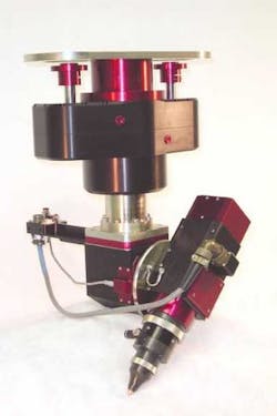
One such system, the Optical Laser Wrist from Haas Laser Technologies Inc. (Flanders, NJ), is a two-axis optical device designed for high-power industrial lasers used in multi-axis laser processing machines, laser robots, and custom equipment (see Figure 1). It uses a two-mirror optical configuration to direct the focused laser beam to the workpiece. Each axis is positioned or rotated by an individual motor, which is controlled by the user's CNC. Because the unit is modular in design, integration is possible for any motor and CNC combination. Each system is custom assembled as per customer requirements. Several quick-change, magnetically coupled, laser process head configurations are available for specific applications. Some laser process head configurations include laser cutting heads, drilling heads, bevel cutting heads, parabolic welding/cladding heads, and heads with an independent auto-focus axis for capacitive height sensing applications. Other additions include slip-ring options for electrical, water, exhaust, and assist gas connections. The units are available in 25 mm and 50 mm clear apertures and can be customized for any application and laser wavelength.
Recently the aircraft industry has incorporated optical laser wrists and industrial lasers for manufacturing lighter-weight fuselage panels to increase the aircraft's efficiency. The weight reduction process is performed via chemical etching. The physical size of some of these panels requires custom, large envelope, gantry motion systems and optical laser wrists to perform the laser process.
The process starts by placing a layer of chemical etch maskant on the panel. Then the laser precisely scribes complex patterns through the maskant and not into the material base. The laser-scribed patterns are complex geometric shapes engineered to meet specific strength and weight requirements.
Once the fuselage parts or panel sections are scribed, the panel is then removed from the fixture and moved to another station, where the maskant is removed for the etching process. The etching process then removes unnecessary material leaving the desired structure. It is important that the laser cut through the maskant completely and to close all sections so that the removal of the maskant does not lift any adjacent sections of the maskant. Lifting would allow the etchant to penetrate under the maskant and remove desired material.
Several hundred different fuselage panels are processed by this innovative system. Typical panels have a single curve, however some have nonsymmetrical shapes and/or double curvatures.
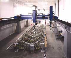
PaR Systems Inc. (Shoreview, MN), a manufacturer of standard and custom robotic systems, (see Figure 2) recently built a large envelope (9 m × 4.5 m × 1.5 m) 9-axis gantry system for aircraft chemical maskant scribing. The MR 125 system incorporates a custom dual-mast laser scribing and drilling system integrated with a flexible fixture. One mast incorporates a Coherent (Santa Clara, CA) CO2 laser and a Haas Laser Technologies Inc. optical laser wrist with an independent auto-focus Z-axis to perform laser scribing. The second mast is capable of registering multiple tools to set the fixture, measuring the part position, and drilling holes in the panel. A custom software package with three-dimensional modeling and post-processing software forms the synergetic union of the fixture and the robot's dual mast capabilities.
The process starts with a programmer working with the CAD software and simulation software package. The programmer places a virtual part onto the fixture and the software determines the fixture support positions. Once in position, the CAD software converts the geometric patterns into three-dimensional machine space with two rotational laser wrist positions for the laser scribing. Similar algorithms determine the positions of holes for four different bit sizes. The modeling system enables the programmer to move a 3D part onto the fixture and witness a virtual model of the robot's mast motions through all three robotic functions; fixture setup, laser scribing, and hole drilling. This modeling allows the operator to visually witness the motion, confirm the robot paths, and minimize part/robot collisions. Once the model is accepted, the robot positions and patterns are converted from engineering drawings to robot commands with a three-dimensional post-processing software package. The robot commands are downloaded to the robot through a network connection ready for processing.
At the robot, the operator selects the required part and the robot software determines the required fixture reconfiguration. The robot keeps an active database of information for both the fixture and the robot. So to save time, the robot determines if the next part is similar or different and will change only the necessary supports.
Once the fixture has been configured for a particular part, the part can be loaded into the fixture. When the panel is seated on the fixture the laser is activated and moves over the part scribing thin lines through the maskant. After the panel has been scribed, the drilling mast will select the desired bit and drill holes into the panel. The robot is capable of selecting four different bit sizes.
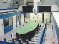
Le Creneau Industriel, (PAE des Glaisins, Annecy-le-Vieux, France), is a manufacturer of three- and five-axis machining centers (see Figure 3) for routing and drilling aluminum and large dimension composite components for the aircraft industry. The company recently installed a new Creno UGV five-axis machine with overhead moving gantry, CO2 laser, and optical laser wrist for a major aircraft manufacturer for laser scribing maskant prior to chemical machining.
The system, which incorporates a Coherent 100W CO2 laser and a Haas Laser Technologies Inc. Optical Laser Wrist is designed with a large 9 m × 4.5 m × 1.5 m work envelope moving gantry. It incorporates a Siemens 840D CNC with linear motors to provide high accuracy with speeds up to 60 m/min. The curved component to be laser processed is placed on a 99-peg support fixture where each peg has its own independent numerical axis to form the precise 3D shape required. The optical laser wrist is supplied with an independent auto-focus Z-axis (sixth axis) to quickly respond to focus position corrections and complex workpiece structures without collisions. This wrist also incorporates a measurement probe to confirm the actual shape of the component prior to being laser processed. The result is compared to the theoretical shape within the system's software for quality control. The complex pattern is scribed up to 30m/min with an accuracy of ±0.001 in. The laser process is kept smoke-free and the scribed line is kept clean through the use of the smoke extraction hood installed on the optical laser wrist.
Conclusion
In addition to aircraft applications, optical laser wrists are routinely used in several industrial laser applications to process complex, multidimensional components. Modular designs allow the units to be built to specific customer requirements with easy integration to any CNC. With a current worldwide installation base, the optical laser wrist technology has been proved to open new applications and provide new solutions to industrial laser processing.
Gilbert J. Haas, president of Haas Laser Technologies Inc., Flanders, NJ, can be contacted via telephone at 973-598-1150 or email at [email protected]. PaR Systems Inc. can be contacted via telephone at 651-484-7261. Le Creneau Industriel at Construction de centres d'usinage a commande numerique can be contacted via telephone at +33 450 64 03 85.